
Warfighters on the frontlines of the battlefield typically have to rely on communication with distant and remote radio direction finding (DF) assets to obtain tactical information about the location and strength of the enemy. The sheer bulk and weight of traditional direction-finding antenna arrays and their processing equipment, let alone large mast-mounted anten-nas that give away their location, have limited their suitability for battlefield de-ployment, relegating them instead to rear areas or airborne or shipborne stations, or in some cases, behind the frontlines as strategic assets.
A team of engineers from the Tactical Products Department of the Signal Exploitation and Geolocation Division at Southwest Research Institute (SwRI), using internal research funding, is designing and developing novel direction finding antenna arrays to help alleviate this problem. Significant electromagnetic numerical modeling is employed in this effort using CAD software. Two such products recently developed are the AVM-375 DF Antenna Set and the AP-460 DF “Tent” antenna. The AVM-375 consists of up to four low-profile DF sub-arrays that are distributed around the body of military vehicles, providing “on-the-move” DF capability with low visible signature. The AP-460 is a patented human-transportable direction-finding antenna array made of conductive fabric that collapses and stows into a soldier’s backpack for easy transportation. Along with new and innovative antenna arrays, SwRI engineers also develop advanced DF processing architectures and software that run on field-programmable gate arrays (FPGA) in low size, weight, and power (SWaP) configurations. Together, these advanced technologies are helping bring direction finding systems to the frontlines.
Vehicle-mounted, low-profile antenna sub-arrays
Adding traditional direction finding equipment onto military vehicles, such as the high-mobility multipurpose wheeled vehicle (HMMWV, or Humvee®), requires an antenna array on a mast that extends significantly above the vehicle to get it away from external clutter located on the vehicle’s roof. For the Humvee, one such clutter agent is a rotating turret which, because of its rotating nature, cannot be removed through calibration. Elevating the antenna severely limits vehicle mobility and also reveals its mission. SwRI’s solution was to distribute groups of linear DF antenna sub-arrays around the vehicle’s body, each consisting of miniature low-profile directional antenna elements. The arrays face outward, away from vehicle clutter. Any remaining effects from the vehicle can be remedied through calibration. A new version of SwRI’s beam-steer vector match (BSVM) DF algorithm was developed specifically for distributed arrays, removing the effects of inter-array spacing from the DF solution.
The AVM-375 DF antenna set comprises four sub-arrays, each containing three antenna elements per band, linearly aligned behind a conductive backplate. The backplate, in addition to serving as the mounting mechanism, provides an electromagnetically reflective surface to shield the array from scattering effects coming behind the array and also to give the individual antenna elements more directivity facing out from the backplate.
Patrick J. Siemsen is a principal engineer in SwRI's Signal Exploitation and Geolocation Division. He has been involved in the design of shipboard and land-based direction find-ing systems with both military requirements and rugged commercial requirements. He has led the development of low radar cross section shipboard direction finding antennas, a body-worn DF antenna vest and vehicle-mounted and human-transportable DF antennas for tactical field applications.
The sub-arrays—with one facing front, rear and two broadside—work together to provide 360-degree coverage. Two different antenna element types are used: balanced-shielded loop antenna elements to cover VHF frequencies and tapered-slot antenna (TSA) elements for UHF. Each sub-array design was 30 inches long by 7.5 inches tall by 3.5 inches deep for this platform.
The novel approach was proven through a government-sponsored demonstration on a Humvee. Because of specific mission constraints, the front- and rear- facing arrays had to be moved to the sides of the vehicle for this installation. Two of the sub-arrays were custom-designed to fit behind the front fenders. The remaining two sub-arrays were moved closer to the rear of the vehicle but faced broadside. Although not ideal, 360-degree coverage was still provided. The sub-arrays were mounted using existing bolt holes wherever possible to facilitate ease of installation. Cables were routed underneath the fender skirts and into the vehicle’s interior through existing holes in the body. Other installations on the vehicle included a reference discone antenna (so named because it comprises disc-shaped and cone-shaped elements), a wireless modem antenna and dual GPS antennas. The reference discone antenna and the wireless modem antenna were mounted on posts on the rear of the Humvee. The dual GPS antennas were mounted to the hood.
A miniaturized processor using SwRI-developed DF architecture and software was installed in the vehicle’s cab and a laptop computer provided visual display of reported lines of bearing. The DF processor operated from battery power, but could also be powered through the vehicle's own power distribution. The RF cables from the antenna arrays connected directly to the processor.
Engineers calibrated the system by turning the vehicle around in circles while collecting calibration data at specific frequencies. Only a single calibration is needed for installation of a given platform type, as long as the sub-arrays are installed the same way.
Vehicle heading information was provided during the demonstration by a dual GPS antenna array mounted on the hood. The demonstration involved driving around the SwRI antenna field site while collecting DF data on a number of fixed and hand-held transmitters at the site. DF lines of bearing were collected in both a DF mapping mode and a data logging mode. For the DF mapping mode, lines of bearing were continuously displayed on a satellite map of the SwRI field site, emanating from the location of the vehicle as it was driven. For the data logging mode, continuous calculated lines of bearing and actual direction of arrival (calculated from knowing the latitude and longitude of both the transmitter and the Humvee) were logged to a data file for post-processing, from which DF error was obtained. Additional DF tests were performed on over-the-air signals and while rotating the vehicle’s turret. Finally, “fox hunts” were performed, where the vehicle crew would search for a hand-held transmitter at an unknown location.
Stationary DF testing prior to the demonstration, with the vehicle sitting on a rotator, yielded an overall RMS DF error across frequency of 3.8 degrees. For mobile testing, the 68th percentile (one standard deviation) of the DF error averaged between 5 and 10 degrees. DF results collected during the demonstration matched closely with those results.
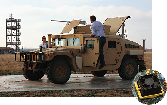
Optimal locations for mounting direction finding antennas on tactical vehicles like the Humvee are complicated by signal interference from combat equipment mounted atop the vehicle, and also by the need to miniaturize its onboard electronic signal processing system (detail inset).
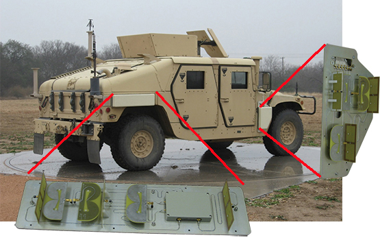
Portions of an SwRI-designed AVM-375 antenna system’s sub-arrays are shown with their protective radomes removed, and as mounted on a vehicle, beneath light tan-colored radomes that are visible here ahead of the front door and at the right-rear corner.
Human-transportable “tent” antenna
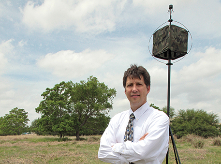
The logistics and transportation of DF equipment to the front lines of the battlefield are rather difficult given its traditional large size and extreme weight. In addition, the setup process is painstaking. The SwRI-designed AP-460 DF “tent” antenna is a lightweight, collapsible, human-transportable DF antenna specifically designed for tactical field applications, where the operator requires quick setup and teardown time (less than 5 minutes). The antenna elements and associated cabling are fully integrated into a cube-shaped fabric structure (the “tent”) that collapses and stows into a soldier’s backpack. Antenna elements are made from conductive fabric and small printed circuit boards. The total weight is less than 5 pounds. The antenna is mounted on a tripod with mast that extends 20 feet above the ground. The tent portion is supported to the mast using shock-corded fiberglass poles much like those that campers use to support their tents.
The tent structure is cube-shaped, with four outward faces made of polyester mesh material supported by a flexible, flat-spring steel outer frame around each face. The top and bottom are open.
The AP-460 DF antenna provides full coverage across the VHF/UHF frequency ranges in three separate but concentric antenna arrays fabricated into the single pop-up structure. Each antenna array covers a different portion of the operating frequency range. The lower frequency array covers from 20 MHz to 160 MHz and is made up of four shielded loop antennas, one on each face of the structure. The loop antennas are made from flexible RF cable routed through channels sewn around the outer edge of each face. Small circuit boards serve as the feed points and electrical gap for the shielded loops. The middle frequency array covers from 160 MHz to 650 MHz and consists of eight bow-tie type anten-nas, with two on each face. The bow-tie antenna elements are made using conductive cloth material sewed directly onto each face. The higher-frequency array covers from 650 MHz to 3 GHz and consists of eight tapered slot antennas, with two on each face. The tapered slot antenna elements are made out of circuit board material that fits into pockets sewn onto the faces. All circuit boards are small enough so that the structure can still collapse.
The same processing equipment used with the Humvee-mounted antenna can be used with the tent antenna. Power can be provided through solar-rechargeable military radio pack batteries. With the DF processor, the tent antenna produces exceptional DF line-of-bearing (LOB) accuracy of better than 5 degrees RMS across the operating frequency range.
Advances in FPGA processing technology
Through SwRI‘s internally funded research program, a joint software/firmware “system on a chip” (SOC) processing architecture has been developed that uses field-programmable gate arrays (FPGA) in a low size, weight and power (SWaP) configuration. FPGAs are integrated circuits that can be configured after manufacture. The low SWaP is a key requirement for deploying the technology on small, tactical platforms. Unlike previous designs which suffer from low-speed data transfer between the FPGA and the processor, SoC technology eliminates this bottleneck and simplifies resource allocation. Faster FPGA-based digital signal processing capabilities, combined with an expanding array of intellectual property cores and development tools for FPGAs, enable new system architectures and thus new capabilities on small tactical platforms. In addition, portable software libraries running on FPGAs have been achieved for prosecution of wideband communications signals.
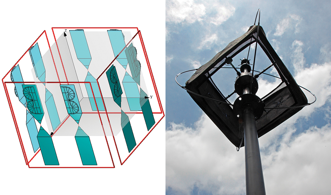
An SwRI-designed AP-460 “tent” antenna is shown alongside the numerical model used for analyzing its performance. Antenna elements embedded in the “tent” lining are evident.
Direction finding missions
These products have applications not only for the military, but also in law enforcement, border patrol and other functions. A number of government agencies have expressed interest in these products. External funding has recently been secured for application of the AVM-375 onto a helicopter platform. As with the Humvee, the DF sub-arrays are custom-fitted to the vehicle’s unique mounting requirements.
The complete SIGINT/DF sensor for mobile platforms, including ground vehicles, aircraft, UAVs, and others, is made possible by these enabling technologies from SwRI: novel antenna designs and advanced signal-processor architecture.
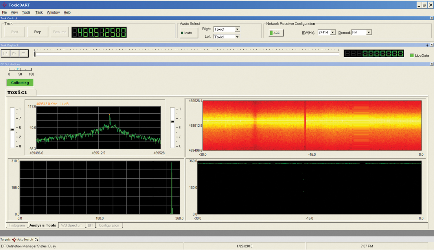
This visual display from the graphical user interface of the field programmable gate array (FPGA)-based DF processor on the Humvee shows the DF spectrogram after rotating the vehicle's turret 360 degrees in azimuth.
Questions about this article? Contact Patrick Siemsen or call +1 210 522 2995.