Submitted by Branson Brockschmidt on Mon, 10/19/2020
In the past two decades, composites have increasingly displaced aluminum as the structural material of choice in the aerospace industry. Previously considered an exotic material confined to high performance military aircraft, composites are now widely used in the civilian sector; the composite airframes of the Boeing 787 and the Airbus A350 being excellent examples. Although the exceptional strength-to-weight characteristics of composites make them ideal for aerospace components, manufacturing and material handling challenges can make implementation of such materials difficult.
Prepreg composites are woven fabric, such as carbon fiber, pre-impregnated with resin and are often formed by hand onto a mold. Manual layup increases costs, especially on complex components such as engine cowlings and control surfaces. Automating layup can help reduce repetitive strain in human workers and lower production costs. However, automating composite layup is a complex challenge requiring machine vision with robotics that can replicate human dexterity.
SwRI is excited to share recent hardware and software developments that show automated layup of prepreg materials is possible.
Hardware Tools Automate Prepreg Sheet Layup
SwRI's robotic solution for prepreg layup utilizes two tools: a patent-pending gripper tool and a consolidation tool. The gripper tool consists of two fingers, each with a roller that can have its resistance to rolling adjusted depending on the operation being performed. For example, the rollers may be locked from rotating if a firm grip on the prepreg material is desired so that it does not droop and prematurely contact the mold. Alternatively, the rollers may be allowed to roll freely to allow the gripper to pull away and release the sticky prepreg material. The consolidation tool, used to press the prepreg to the mold, mimics tools used by workers during manual prepreg layup. The consolidation tool can use various features such as flats and radii to ensure the prepreg is pressed onto every part of the mold. Together, these tools allow for the prepreg sheets to be contoured to three-dimensional molds as shown in the image.
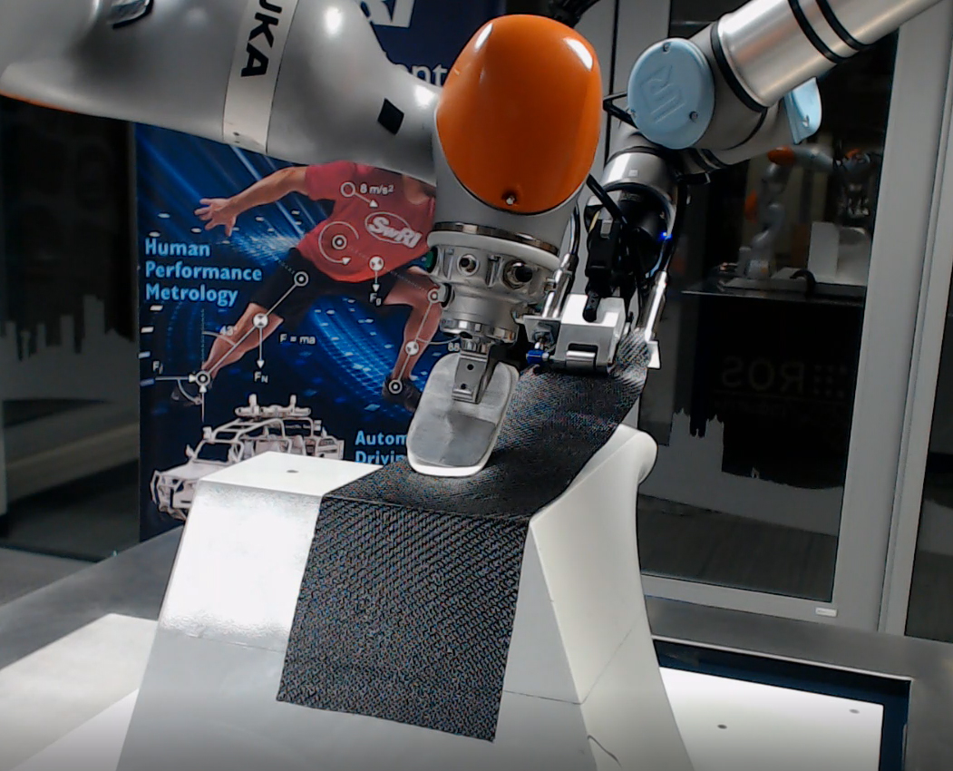
The gripper and consolidation tools perform a prepreg layup test in SwRI's Collaborative Robotics Laboratory.
ROS Path Planning, Machine Vision Software
To control and manipulate both tools mounted to robots, SwRI developed software using ROS frameworks Noether and Tesseract. The robot controlling the gripper tool is manually programmed for individual geometric features such as maneuvering over an edge or traversing over a convex curve. The manually programmed paths for individual geometric features can then be combined to create a robot path for the layup of an entire mold. The robot controlling the consolidation tool has a path automatically generated using a supplied CAD model of the mold. The trajectories of both robots are planned so that their motions coordinate with one another, resulting in a properly laid up prepreg part.
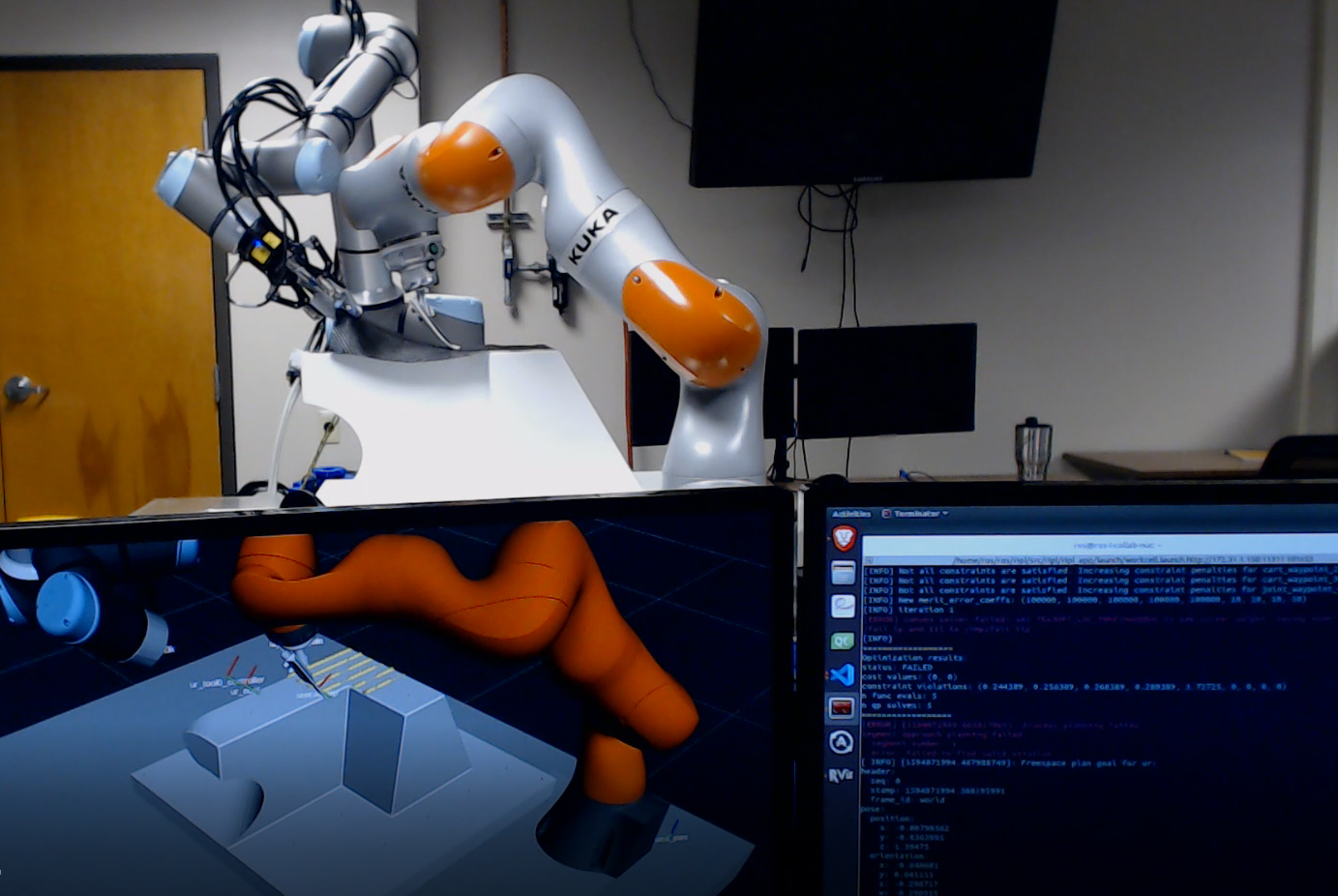
ROS software runs on the computer in the foreground with robots executing a layup process in the background.
One final aspect of SwRI's system is an early stage machine vision system. This vision capability will ultimately provide a quality control system, finding errors such as wrinkles and verifying that the angle of the prepreg fibers match design specification. SwRI has experimented with various lighting sources and image capture techniques, but more work is planned. The ROS software image above shows a sample output of the vision system where an FFT is used to calculate the fiber angle with a resolution of 1 degree.
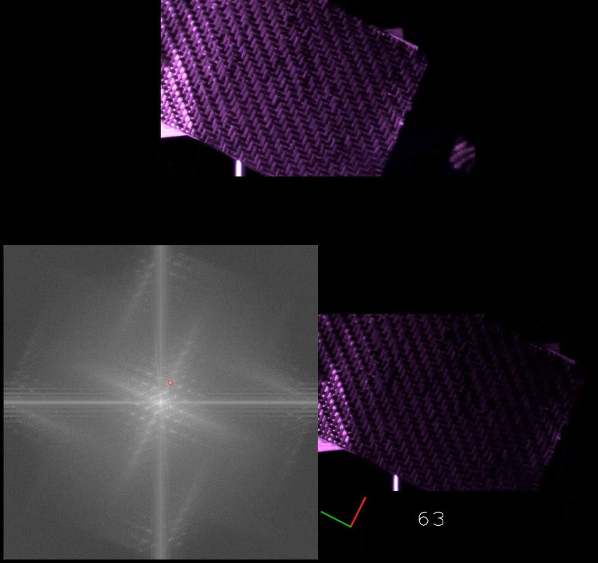
This depicts on-screen output of a captured image, the FFT, and the resulting fiber angle during a test with UV illumination of the prepreg material.
Additional Resources
Learn more about the software for this project in ROS-Industrial blogs here and here. Visit Machine Learning Technologies or Robotics Engineering to find robotics software and hardware solutions.