
Background
Simulation and modeling of internal combustion engines has become the standard in engine development by shortening development time and eliminating some of the hardware iterations that were required twenty years ago. SwRI has developed a combustion model (HEDGE mechanism) for gasoline engines as part of the HEDGE-III consortium and has been applied in 3D Computational Fluid Dynamics (CFD) simulation. Diesel combustion studies have been conducted under the CHEDE-VI and CHEDE-VII consortia.
SwRI has developed extensive procedures for simulating and analyzing cylinder head operation using the finite element approach (FEA). Generally, the combustion CFD and thermal FEA simulations are conducted separately with an interface boundary condition assumption. Because these phenomena are interdependent, separating the numerical simulations brings with it several inaccuracies. The primary objective of this research is to develop and validate a method for improving the heat transfer prediction in the internal combustion engine by coupling the combustion CFD, thermal FEA and cooling CFD. A better heat transfer prediction improves the combustion and wall heat loss prediction.
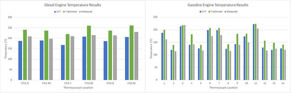
Figure 1: Simulated temperature results, by the conjugate heat transfer and traditional methods, compared to test data for the diesel and gasoline engines.
Approach
Three simulations were conducted concurrently: combustion CFD, thermal FEA and cooling CFD. Because the cyclic variation of the parameters for thermal FEA and cooling CFD is minor, both simulations were conducted under a steady-state mode. The combustion CFD was conducted under transient conditions due to highly transient process inside the combustion chamber. For the interaction, data was exchanged in 120 crank angle degree intervals between the combustion CFD and the thermal FEA models. At each interval, the thermal FEA and cooling CFD models iterated until convergence was achieved. This approach continued for multiple cycles until wall temperature and heat flux convergence was achieved between the combustion CFD and thermal FEA models.
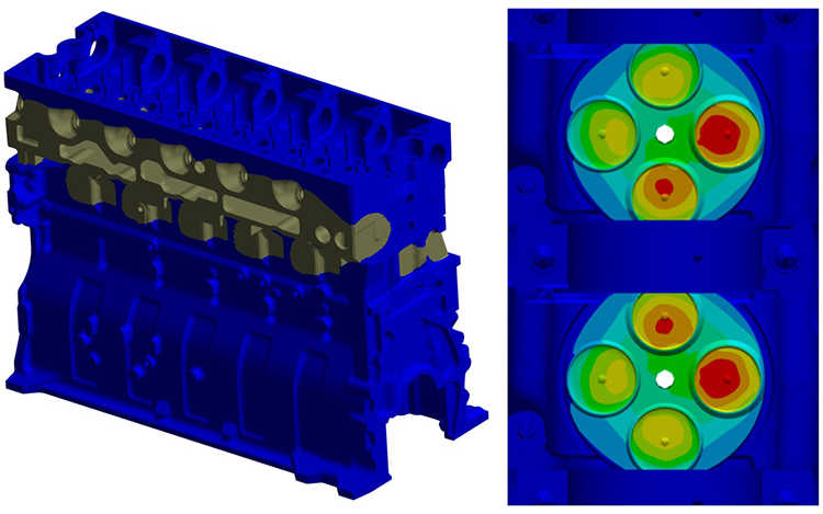
Figure 2: Temperature distribution on the diesel engine as predicted by the conjugate heat transfer analysis method.
Accomplishments
A diesel and a gasoline engine were modelled using this conjugate heat transfer (CHT) technique. Heat transfer models based on experience-based SwRI analysis methods were also setup for both engines. The conjugate heat transfer method demonstrated better temperature agreement than the experience-based analysis methods, a 12.5 percent improvement in accuracy on average. The combustion model for both engines also displayed good agreement with test results for cylinder pressure and heat release rate. The CHT model demonstrated convergence after running 3 cycles of combustion. This analysis method effectively takes three or four days making it cost-effective for use on client projects.
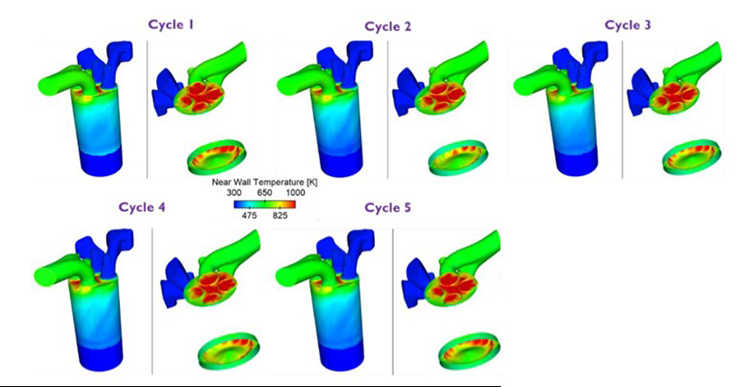
Figure 3: Near-wall Cycle-Averaged Gas Temperature for the Five Simulated Diesel Engine Cycles.