
Background
As engine and powertrain efficiency are pushed to new limits, so are the techniques used to develop them. Recently, SwRI’s Powertrain Engineering Division has completed development and deployment of a dynamic bearing test facility that can simulate the cyclic, 250 bar peak firing pulses of an advanced heavy duty diesel engine. The bearing test facility has enabled cutting-edge lubricant and bearing research by replicating the speeds and forces seen in an internal combustion engine in a way that has never been done before. Current instrumentation includes multiple oil film thickness probes and an inline torque meter for crank angle resolved bearing performance.
After proving the value in acquiring detailed bearing measurements at steady state conditions the next step is to understand what happens during transient events like start-stop and customer duty cycles. While start-stop is found in many passenger vehicle applications, it can be challenging for commercial vehicles and off-road machines due to the extreme operating conditions and long life expectancy. This research project will add enhanced control algorithms and instrumentation so that the bearing test facility can replicate customer duty cycles, in-cylinder pressure, and oil conditions to understand their effect on bearing performance.
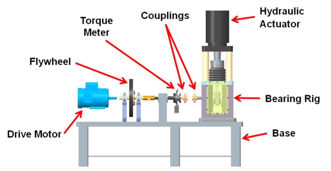
Figure 1: Assembly view of the dynamic bearing test facility.
Approach
Data was collected from heavy duty engines of various sizes installed in test cells. The oil gallery pressure and firing characteristics were recorded as targets for the bearing test facility. Additional oil film thickness measurements and thermocouples were added to the test connecting rod to better capture the journal orbit and predict minimum oil film thickness and location in the bearing. The additional oil film thickness measurements also allow for characterization of the connecting rod large end deflection under very high simulated cylinder pressures. The additional measurements will allow for high fidelity datasets that can be used to calibrate bearing simulation models.
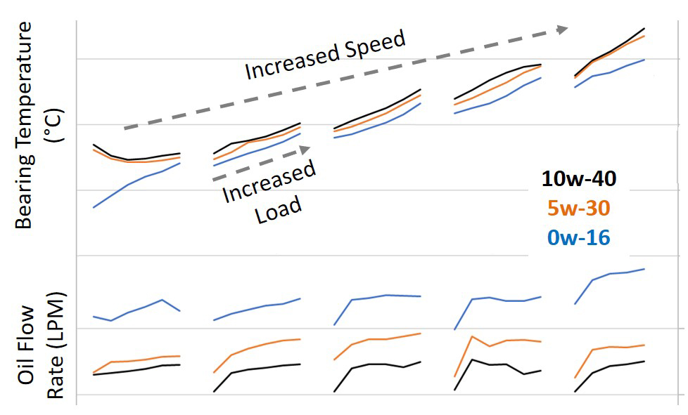
Figure 2: Mapping of bearing oil flow and temperature across the engine speed and load range.
Accomplishments
The controls system has been rebuilt from the ground up with transient testing in mind. It is now possible to take a map of cylinder pressure profiles from a customer and load them directly into the controller where they are converted to bearing force and evaluated autonomously. The bearing test facility will evaluate each profile, automatically learning how to meet the target profile in a matter of seconds. With the map of resulting bearing force as a function of speed and load, customer engine duty cycles are then added and oil film thickness, bearing torque and oil flow are tracked throughout the test cycle. As the project continues, aggressive start-stop strategies will be applied, and the impact on bearing oil film breakdown will be evaluated.
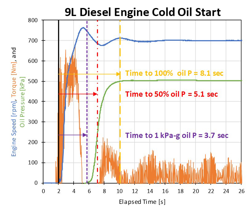
Figure 3: Example of delayed oil pressure rise after engine start.
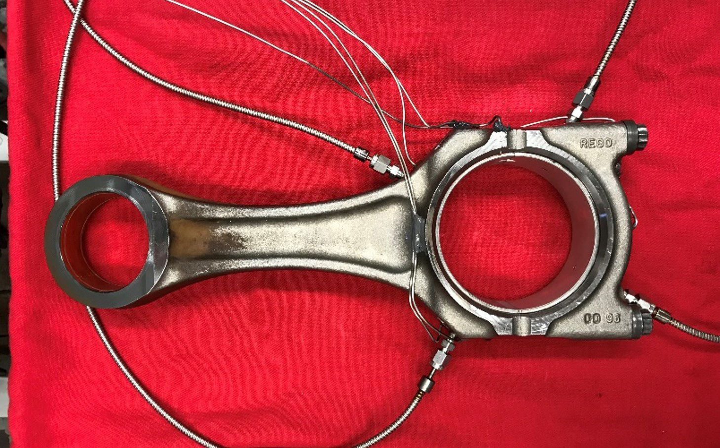
Figure 4: Connecting rod showing four oil film thickness measurements.