Background
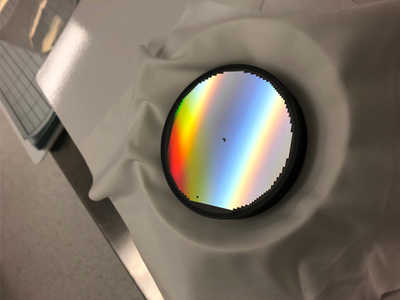 Figure 1: Fabricated spherical grating with aberration correction.
 Aberration-correcting gratings, fabricated with holographic techniques, are a feature of many ultraviolet instruments in space. The ALICE spectrographs, which Southwest has deployed on such NASA missions as New Horizons, are a prime example of the improved performance that is key to competitive proposals.
Traditional aberration-correction is achieved by interfering two recording lasers on a photoresist, creating grooves that can be configured by changing the input angles and distances from the grating to the lasers. The grooves created by holography can have variable spacing that is curved, providing additional optical power in a controlled fashion. By optimizing the location of the lasers in conjunction with the optical performance of the spectrograph, the capability of a given spectrograph may be dramatically improved. However, these techniques have the limitations of quantized and finite laser recording wavelengths. The created grooves have only a few free parameters, and therefore, the grooves are functionally related everywhere on the grating.
Approach
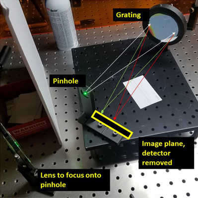 Figure 2: Complex grating in raytrace and test setup.
 With the advent of e-beam grating fabrication, we are in the position of being able to create each groove of a grating individually, with every portion of the grating having the exact correction needed at that point to increase overall optical performance.
The development of optimization software specifically designed to create a groove map is needed to fully exploit the capability of e-beam aberration correcting gratings. No such software existed prior to this project. We will gain raytrace capability by optimizing an aberration-correcting e-beam grating and then demonstrate that grating by fabricating a set of test pieces. Our development process is key to validating our approach.
Accomplishments
Working with Penn State’s nanofabrication lab, we have written two gratings. The first was a flat grating with a Fresnel pattern, to demonstrate that we can successfully export a known groove map with clear grating performance. The component was completed and demonstrated. The second grating, an aberration-corrected version of a Rowland circle grating, was fabricated (Figure 1) and was tested for optical performance (Figure 2, Figure 3).
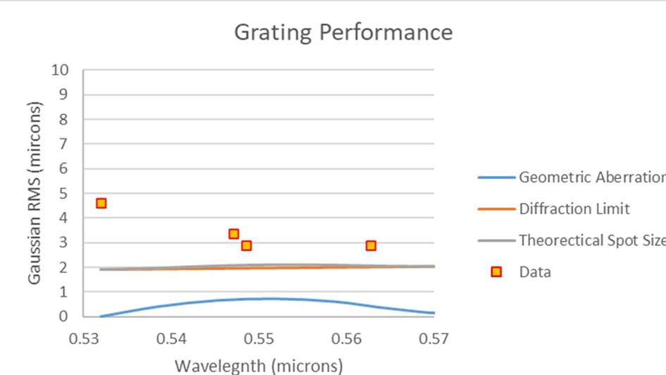
Figure 3: Grating performance over passband. The blue line (Aberration RMS) is the spot size due to purely geometric ray aberrations. The orange line (Diffraction RMS) shows the resulting spot size due to the diffraction from the finite grating size. The root-sum-square shows the theoretical best spot size.