
Background
High-power lasers are being used for an increasing number of industrial and medical applications that require generation of localized heating. One particular application is the removal of paints, sealants, or coating on aircraft, which can be a physically demanding job occurring in confined locations. Removal of these materials is accomplished more effectively at a long wave infrared (LWIR) wavelength of 10.6 µm as generated by carbon dioxide (CO2) lasers. Directing LWIR light onto a surface is usually done by an arrangement of mirrors, but this poses problems when trying to access confined spaces or surfaces with unusual geometries. Fiber optics is commonly used to direct visible light in this way but propagating high optical powers through fibers is a challenging problem in general, exacerbated by the requirement to transmit LWIR light. Few optical fiber options exist at LWIR wavelengths and those that do are not capable of transmitting the needed power.
Approach
Large diameter hollow-core optical fibers, which use a 500-1000 µm glass capillary tube with a specialized metallic coating on the interior surface and a polymer exterior coating, are capable of transmitting up to 100W of LWIR laser light. For a laser de-paint system, much higher power is required, which would destroy the fiber by creating excess heat. The approach being developed involves actively cooling the fiber with circulated chilled water in a flexible sheath that encapsulates the fiber. Copper endcaps are used at the end-faces where the maximum heating can occur.
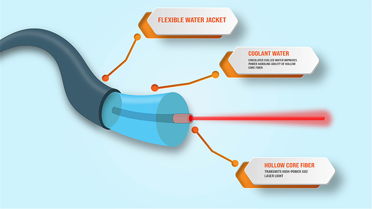
Figure 1: High power CO2 laser fiber concept with a large diameter (1000 µm) hollow core fiber enclosed in a flexible tube with circulating chilled water.
Accomplishments

Figure 2: Thermal profile of an un-cooled optical fiber while being tested with 100W of CO2 laser light. Heating is greatest near the input end of the fiber (at left), but hot spots occur at intervals along the fiber. Lighter color indicates higher temperatures..
Several designs for the fiber cooling loop were mathematically modeled. The optimum design was found to be a simple tube surrounding the fiber. The mechanical design for this approach was created with special focus on the entry point of light into the fiber since this is the most likely failure point. An initial version of the cooling loop design has been fabricated and successfully assembled. We have also been developing techniques to test the fibers with the high-power CO2 lasers available at SwRI. Several commercially available hollow-core fibers have been tested without cooling to measure their temperature profile for refining the cooling models and to assess their LWIR optical power handling capabilities. These fibers will then be integrated into the cooling jacket and re-tested to validate the improvements in power handling.
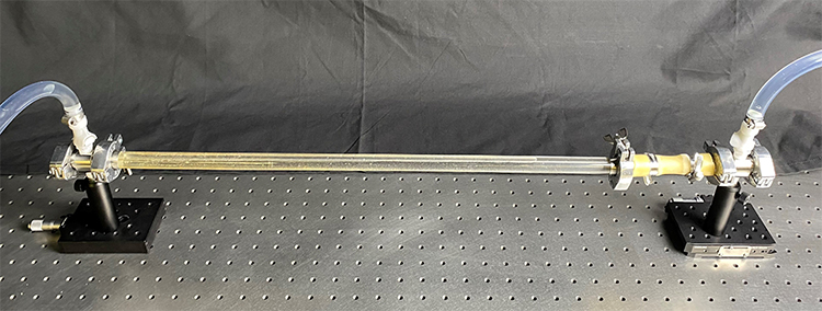
Figure 3: The initial cooling loop for testing the hollow-core fibers. This version includes an acrylic tube to visually observe the fiber during testing.