Background
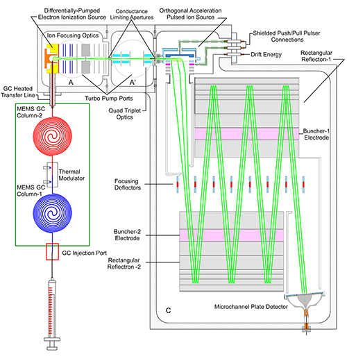
Figure 1. Block diagram of the proposed ion optics coupling the GC to the ZZ-TOF-MS.
Gas chromatography-mass spectrometry (GC-MS) has long been considered a “gold standard” for quantitative analytical analyses of a variety of small molecules. Making these benchtop systems into field-portable instruments would greatly expand the analytical capability of landed space missions in addition to a variety of Earth science based in situ measurement applications. Recently, SwRI has developed the MAss Spectrometer for Planetary EXploration (MASPEX), a sensitive, high resolution mass spectrometer as part of NASA’s Flagship Europa Clipper Mission. Utilizing our previous instrument development heritage, the primary objective of this research is the development of a novel ion optical interface between a gas chromatograph and ZigZag time-of-flight mass spectrometer (ZZ-TOF-MS). Successful instrument development would lead to a compact GC-MS system for identification and quantitation of complex sample matrices for future landed missions at Enceladus, Europa, and Titan.
Approach
SIMION and Molflow simulations are employed to design the ion optical regions of the ion source and ion transfer optics to couple the GC with the ZZ-TOF-MS (Figure 1). The ion source (section A in Figure 1) ionizes the neutral gases separated in the gas chromatograph (GC) and then transfers those ions to a second ion optical region which transmits the ions through a quadrupole triplet (section A’ in Figure 1) into the orthogonal acceleration (OA) source of the ZZ-TOF-MS (section C in Figure 1). The gas loads from the helium carrier gas flow rates of the GC separation are used to determine the pumping capacity and aperture or slit size of each differentially pumped region of the GC-MS interface to achieve lower pressures through each successive region and the lowest pressure achieved in the mass analyzer region. The ZZ-TOF-MS is designed with trade space parameters of size (mass), ion transmission (sensitivity), and mass resolution.
At the end of the project, we plan to couple a micro-electro-mechanical system (MEMS) gas chromatograph, demonstrated on a current instrument development project, to the ZZ-TOF-MS through our novel ion optical interface to demonstrate the proof-of-performance prototype for a future landed mission GC-MS instrument.
Accomplishments
The ion source has been built, assembled, and tested. The ion source ionizes the neutral gases separated in the gas chromatograph (GC) and then transfers those ions to the orthogonal acceleration (OA) source in the ZigZag time-of-flight mass spectrometer (ZZ-TOF-MS). The low mass carrier gas (Hydrogen or Helium) ion removal has been proven through experimental testing. This allows for the target analyte ions of higher m/z range (40 u and above) to be enriched and transferred to the orthogonal acceleration source for mass analysis by the ZZ-TOF-MS. Ion beam current measurements have been made at a channeltron electron multiplier behind the beam-defining slit. The beam current measurements as a function of the half-plate (steering) voltages of the ion source are displayed in Figure 2. A low voltage applied to the left half plate (larger electric field) demonstrates transmission of low m/z ions (H2 and He) through the beam-defining slit, while a higher voltage applied to the left half plate (lower electric field) transmits higher m/z ions (Ne, N2, Ar, and even Xe although the Xe data is not shown). The ion source is operating successfully and will transmit m/z ≥ 40 u with correct half plate voltages. This mass range is the prime target for organic species to be separated by the GC.
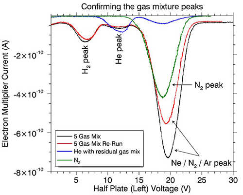
Figure 2. Ion beam current measurements at the channeltron electron multiplier demonstrating successful operation of the ion source including transmission of the correct m/z window to the downstream ion optics and orthogonal acceleration source into the ZZ-TOF-MS.
SIMION simulations were used to determine the overall ion optical design of the ZZ-TOF-MS. An ion ray trace overlaid on a 2-D CAD view of the ZZ-TOF-MS within its vacuum chamber is displayed in Figure 3. Figure 4 provides a 3-D isometric CAD view of the ZZ-TOF-MS with labeled elements. The ion source, discussed above, would be mounted above the orthogonal acceleration source on the lid of the vacuum chamber. Ions created in the ion source would be transmitted downward into the orthogonal acceleration source where they are pulsed out orthogonally into ion packets that separate in the ZZ-TOF-MS according to their m/z value (velocity from KE=1/2mv2 with uniform kinetic energy provided to the ions). The orthogonally accelerated packets follow a zigzag motion through the ZZ-TOF-MS until they strike the MCP detector (Figure 3). We plan to implement two potential mounting positions of the detector (Figure 4); the second position provides a return zigzag pathway for increased flight length and thus higher resolution. However, for the remaining scope of this IR we will most likely test the ZZ-TOF-MS only with the first detector position.
Much of the hardware has been fabricated in SwRI’s two machine shops, Division 18 Machine Shop (Building 162) and the Division 15 Machine Shop (Precision Machining Facility, Building 270). The status of the hardware, labeled in Figure 4, is denoted by the color of the text. Hardware that has been fabricated is in green text, in the process of fabrication is in yellow text, and yet to be submitted for fabrication is in red text. Once the hardware is completed, assembly of all hardware in the vacuum chamber will be performed and proof-of-concept testing will begin to demonstrate the performance of this new GC-MS instrument platform.
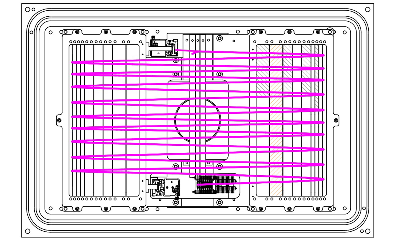
Figure 3. Ion ray trace displaying the ion flight path in the ZZ-TOF-MS overlaid on a 2-D view of the CAD model.
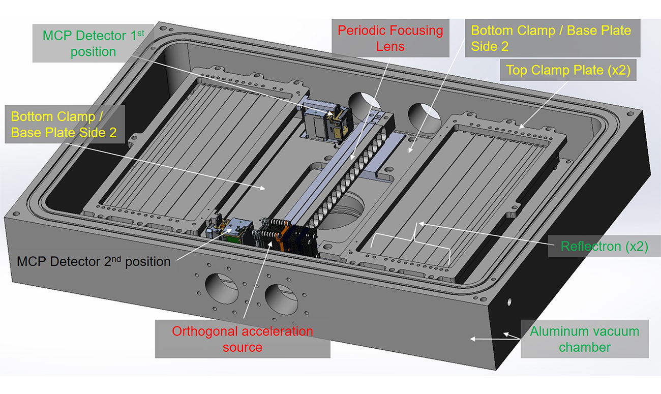
Figure 4. 3-D isometric CAD view of the ZZ-TOF-MS within the Al vacuum chamber. The labeled components are color coded to describe the hardware status (fabricated = green, in the process of fabrication = yellow, yet to be submitted for fabrication = red).