Background
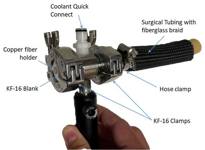
Figure 1: This fixture was designed for mounting and sealing the HCF to the cooling tube and to provide a connection interface for the chilled water.
High-power lasers are being used for an increasing number of industrial and medical applications that require generation of localized heating. One particular application is the removal of paints, sealants, or coating on aircraft, which can be a physically demanding job occurring in confined locations. Removal of these materials is accomplished more effectively at the long wave infrared (LWIR) wavelength of 10.6 µm as generated by carbon dioxide (CO2) lasers. Directing LWIR light onto a surface is usually done by an arrangement of mirrors, but this poses problems when trying to access confined spaces or surfaces with unusual geometries. Fiber optics are commonly used to direct visible light in this way but propagating high optical powers through fibers is a challenging problem, in general, exacerbated by the requirement to transmit LWIR light. Few optical fiber options exist at LWIR wavelengths and those that do are not capable of transmitting the needed power.
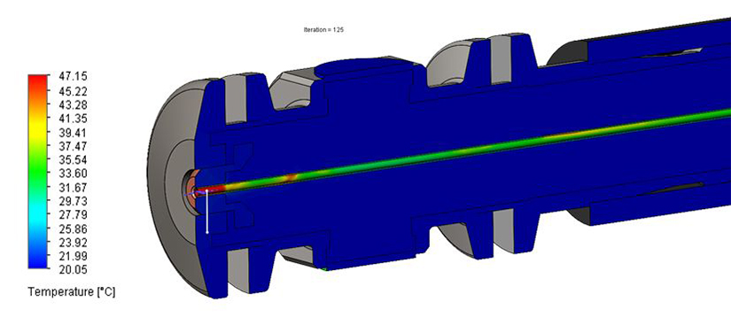
Figure 2: A thermal simulation was performed of the end face of the water-cooling tube and an HCF with 1 kW of input optical power showing the temperature of the fiber should not exceed 50°C.
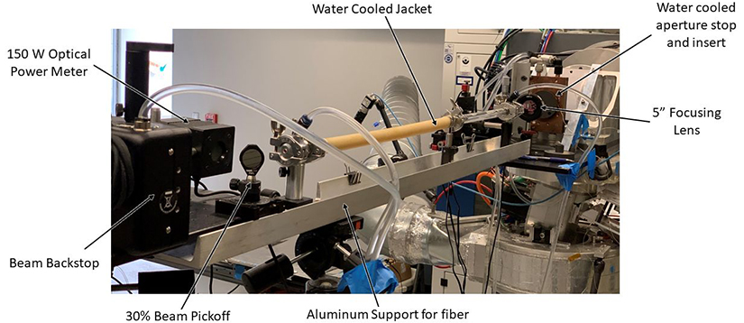
Figure 3: This experimental setup was used for testing the cooled hollow-core fibers with the 20 kW CO2 laser.
Approach
Large diameter Hollow-Core optical Fibers (HCFs), which use a 500-1,000 µm glass capillary tube with a specialized metallic coating on the interior surface and a polymer coating on the exterior, are capable of transmitting up to 100 W of LWIR laser light. For a laser de-paint system, much higher power is required, which would destroy the fiber by creating excess heat. The approach being developed involves actively cooling the fiber with circulated chilled water in a flexible sheath that encapsulates the fiber. Copper endcaps are used at the end faces where the maximum heating can occur.
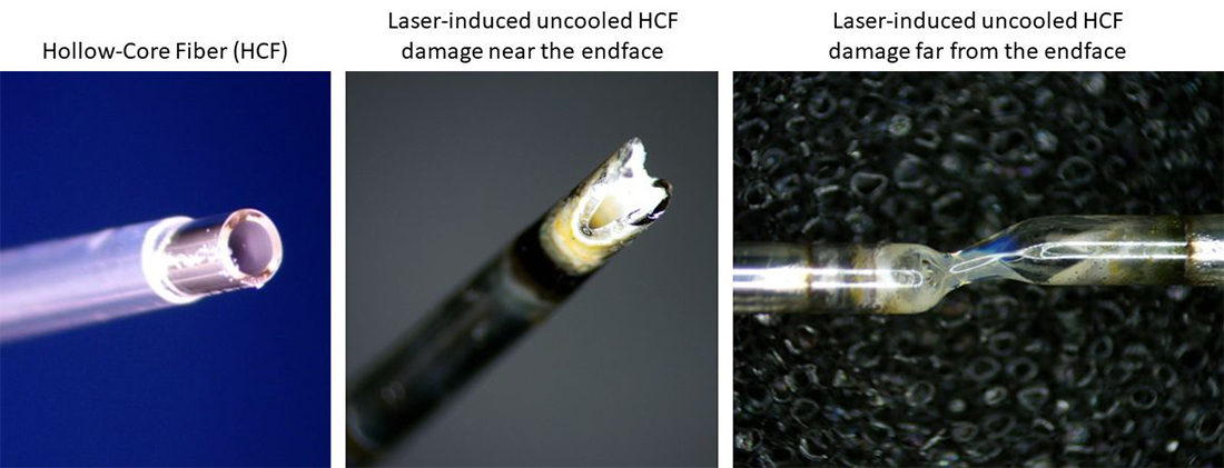
Figure 4: Uncooled HCFs exhibited two distinct damage locations when exposed to excessive optical power. At left is an un-used HCF while the center and right view show damage at the end face location and at 17 cm from the end face, respectively.
Accomplishments
Figure 5: This thermal infrared video shows the heating and failure of an un-cooled HCF when exposed to CO2 laser light in excess of 160 W. Temperatures are shown in the scale at right.
Several designs for the fiber cooling loop were mathematically modeled. The optimum design was found to be a simple tube surrounding the fiber. The mechanical design for this approach was created with special focus on the entry point of light into the fiber since this is the most likely failure point. Fibers were rigidly mounted to the end fixtures and tensioned within the tubing to ensure they remain concentric. A chiller circulated water at a 5 psig inlet pressure at 20°C. The fibers were tested in 1-meter lengths using a 20 kW CO2 laser modified for reduced power output. Power output was incrementally increased until failure was observed with the output power monitored via a beam splitter and optical power meter. For uncooled fibers, the average power to cause failure was 183 W. The failure location was binary, either being at the input end face or about 20 cm from the end face. For the cooled fibers, the average failure power level was 253 W. Most failed near the input end face but others failed between 10 and 30 cm from the end face. Although the cooling increased the HCF’s power transmission, thermal modeling indicated it should be able to handle much more optical power. It is suspected the discrepancy was largely due to the highly non-uniform mode structure of the high-power CO2 laser. A scaled up conceptual design was created for up to 21 fibers to handle much higher powers.
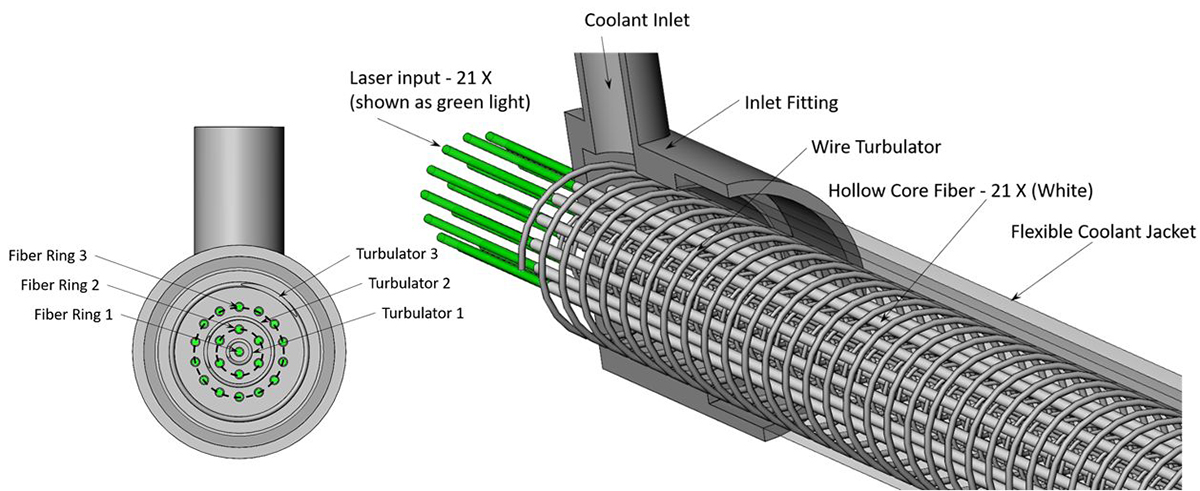
Figure 6: A conceptual multi-fiber design was prepared for transmitting much higher powers in parallel HCFs.