Background
Corner Reflector Interferometric Synthetic Aperture Radar (CRInSAR) geospatial remote-sensing technology has enabled precise monitoring of infrastructure movement due to material fatigue and geologic land surface deformations. Conventionally, CRInSAR uses three-dimensional trihedral corner reflectors to provide detectable, measurable targets at the desired infrastructure locations. However, the corner reflector has a cumbersome three-dimensional form factor that makes it difficult to install and maintain during extended monitoring periods.
To address these issues, SwRI made significant progress toward the development of an easier to install and maintain two-dimensional retroreflector based on the Van-Atta (VA) principle. In that work, a flat Van-Atta array was developed. However, to facilitate array reconfigurability and Radar Cross Section (RCS) testing, coaxial cable transmission lines were used. The consequence of this is that the SwRI retroreflector does not have a true two-dimensional structure (Figure 1). In this work, the objective is to embed the transmission lines into the array substrate to achieve an integrated two-dimensional array structure.
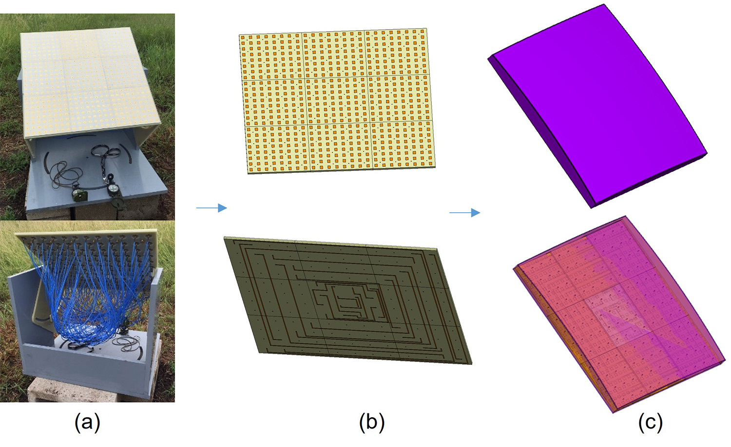
Figure 1: SwRI Van Atta array (a), depiction of 2D Van Atta array with embedded delay lines (b), depiction of weather resistant Van Atta array in radome housing (c).
Approach
The coaxial lines are being replaced by a novel transmission line design based on a hybrid approach implementing Substrate Integrated Waveguides (SIW), strip-lines, and micro-strip lines. The transmission lines will be embedded within the array substrate. Design constraints require that the lines have low loss, high isolation, and must be phase matched. A scalable solution that can be applied to different frequency bands (L, S, C, X) is a development goal. 3D full wave electromagnetic modeling and simulation are being used in the development work. The goal is to develop and fabricate a 16-element and a 64-element Van-Atta array prototype. The prototypes will be tested in the laboratory and will be made available for field test and evaluation.
Accomplishments
Transmission line designs for a 16 and 64 element Van-Atta array have been designed using micro-strip and strip-line transmission lines (Figure 2a). Modeling and simulation reveal that the transmission line insertion losses are too high and will therefore reduce the array RCS performance. In addition, simulation results indicate that the transmission lines will have to be shielded to provide the high isolation required for use in Van-Atta arrays. To address these issues, a SIW transmission line design is being developed. Modeling and simulation show that the SIW insertion loss and isolation performance will meet the design requirements. The partial SIW design for a 16-element Van-Atta array is shown in Figure 2b. Currently four of the SIW lines have been implemented in the layout. The challenge with this design is to achieve the required line to line phase matching. SIW phase shifting structures are being researched to help complete the layout of the remaining four SIW lines.
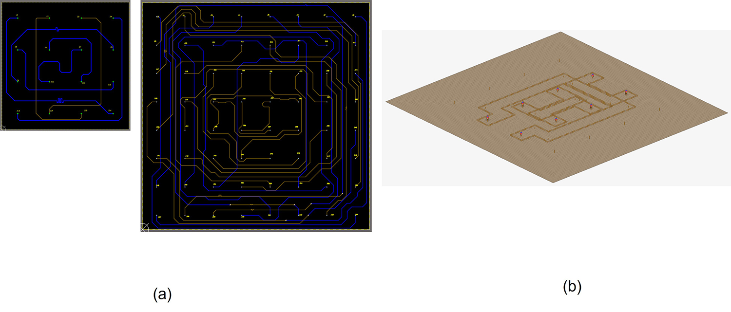
Figure 2: 4x4 and 8x8 micro-strip/strip-line transmission line designs (a), partially completed 4x4 SIW transmission line design (b).