
Small, autonomous unmanned aerial systems (UAS) have grown increasingly popular for varied applications, both military and civilian. Besides surveillance and weapons delivery systems, they are useful in crowd management, air sampling, aerial imagery, and environmental and wildlife surveys. Typical unmanned vehicles tend to be smaller, quieter and less conspicuous than manned aircraft, and they can be operated in environments that are too toxic or dangerous for human operators. However, their relatively small fuel volume limits both their range and performance. Electric-powered vehicles, which excel where quiet operation is desired, are limited even more by battery weight and frequent recharging.
The search for a quiet UAS with adequate speed and range requires a reconsideration of traditional power plants. In response to a government client’s request to develop such a system on a relatively short schedule, an interdivisional team of engineers was formed at Southwest Research Institute (SwRI). The team developed a novel, hybrid power system that combines the speed and range of turbine power with the lower noise level of electric power. The lightweight gas turbine generator, when combined with an electric propulsion system, allows the aircraft to reach distant targets quickly and efficiently.
The SwRI team custom-designed, built and tested a novel gas turbine to drive an electric generator. The hybrid electric configuration allows the UAS to operate using either the gas turbine or the battery and electrical system for propulsion. Including a gas turbine greatly extends the operating range compared to a traditional electrically powered UAS.

John Bishop (left) is a program manager in the Applied Physics Division. His focus includes projects that develop various types of vehicles and other mechanical support equipment. He also develops test systems and procedures and analyzes test results. His experience includes design and testing of gas turbine engine compressor components.
David Ransom (right) is manager of the Machinery Structural Dynamics Section within SwRI’s Mechanical Engineering Division. His research interests include dynamic system modeling and analysis, experimental programs and root cause failure analysis. His work is divided between the energy industry, including hydrocarbon-based and renewable technologies, and the aerospace industry, primarily focused on liquid and air-breathing propulsion.
Hybrid UAS design challenges
The SwRI team designed a fuel-to-electricity generator using a single-shaft gas-turbine generator system that originated with an earlier, non-flying patented SwRI gas-turbine configuration. Repurposing the original SwRI gas turbine generator design required five major iterations and many hours addressing design elements such as layout, rotor dynamics, aerodynamics, mechanical components, combustor design, lubrication and fuel systems and noise control.
The final fuel-to-electricity generator integrated a commercially procured generator/motor with the SwRI-designed-and-built gas turbine system. Throughout the extensive design process, engineers evaluated each design iteration for factors such as weight, performance and manufacturability. Although the gas turbine system is relatively conventional, the fifth and final design concept incorporated a number of unique features.
Because of the high rotation speed of the SwRI gas turbine, the rotordynamic design was a critical element. SwRI’s plan was to develop a simple, single-rotor system with minimal separate lubrication system requirements. In addition, the design team wanted a simple, integrated motor-generator system. The gas turbine generator was modeled and analyzed, with numerous changes to the shaft configuration, bearing sizes, location and shaft damping. In the final configuration, the bearings are located on either side of the rotor with an over-hung compressor and turbine system. The analyses indicated that a softly supported bearing structure on the motor inlet was necessary to improve shaft dynamic response.
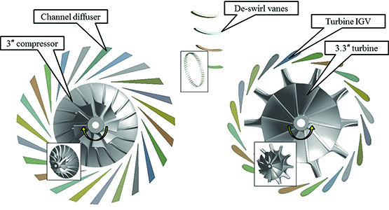
This drawing shows how the gas turbine’s aerodynamic components were designed.

A cutaway drawing shows the final design configuration for a gas turbine generator.
Components of the turbine system were designed using commercial off-the-shelf software intended for detailed aerodynamic, mechanical design and analysis of gas turbine components. During the preliminary aerodynamic design process, the SwRI team estimated mechanical stress to ensure the proposed aerodynamic design would operate at reasonable stress levels. Once the final (or nearly final) aerodynamic configurations were set, all rotating components were subjected to detailed stress analysis. The overall design process was structured to eliminate as many iterations as possible. SwRI engineers developed the aerodynamic designs of the compressor (rotor and diffuser) and the turbine (rotor and nozzles) using 1D and 3D aerodynamic design tools. Similar tools were used to analyze and design the remaining portions of the primary flow path, from the inlet of the engine through to the exhaust.
The SwRI team did an extensive investigation of existing combustor configurations and also studied fuel mixing times, evaporation rates and the combustion process. The combustor was modeled and analyzed using computational fluid dynamics (CFD) modeling. The design team eventually settled on a conventional annular combustor with a liner. Because the combustor is very small, the orientation of the fuel nozzles was adjusted to maximize the spray area volume while minimizing the number of nozzles. The extensive analyses yielded a high degree of confidence that the combustion would light off and burn effectively and efficiently and not fail unexpectedly.
Component mechanical analysis
The component design process included a broad range of analyses to investigate the effects of mechanical stresses from angular velocity, thermal stress, interference fit for stress and assembly/stack tolerance, tie bolt stress, and fit and modal vibration.
Once the static and rotating com-ponents were designed, the SwRI team performed a final modal frequency analysis of rotating components to verify any potential for blade excitation from static components. The interaction between static structural components and rotating components could result in vibrations of the wheels, the turbine disk or the blade surfaces. Because the wheel is fairly rigid, the main area of concern was excitation of either the compressor or turbine blades. Without this critical step, the final design could easily suffer a component failure.
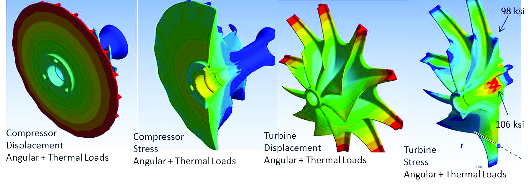
Computation modeling analyzed stress and deflection for angular velocity and thermal loads for turbine disk designs.
Selecting and integrating the motor-generator
Given the focus of the project on the design and build of the gas turbine system, the team sought out a commercially available motor-generator system that would not require excessive development. Although the aerodynamic portion of the gas turbine system can incorporate very high shaft speeds (around 250,000 rpm), the most viable motor-generator available for use in this project had a maximum safe operating speed of 118,000 rpm; therefore, this became the design operating speed for the new gas turbine.
To minimize weight, package size and complexity, the SwRI team integrated the motor-generator into the SwRI-designed gas turbine. To meet the program’s compressed schedule, the motor-generator’s final rotor design configuration was done in parallel with the gas turbine design, using an unfinished motor-generator rotor from the supplier. In the end, the parallel development project resulted in a well-integrated motor-generator and gas turbine system.
Unique features
An interesting feature of the power plant is the two-bearing support system on either side of the motor-generator, and an overhung compressor and turbine. The hybrid system uses ceramic bearings located on either end of the motor-generator’s rotor with a minimal lubrication scheme. Typical oil lubrication systems require the circulation of a significant amount of lubricant through the bearings and then back to a sump for cleaning, cooling and pumping. They require more shaft space to meet the sealing requirements and additional hardware associated with cooling, cleaning, storing and pumping the lubricant. A minimal lubrication system, on the other hand, slowly drips oil into the bearing system, reducing the oil flow rate by two orders of magnitude. It is an open-cycle system in which the lubricant becomes a consumable during the gas turbine cycle. The low oil flow requirement allows a very simple lubrication scheme where the oil and cooling air are pulled through the bearings and into the gas turbine with no adverse effects. This bearing system is simple and minimizes the losses that would exist in a machine with multiple shafts, additional bearings and a typical jetted lubrication system.
Another feature simplifies cooling the generator during operation by using com-pressor inlet air. The resultant heating of compressor inlet air by 5 degrees F creates a small performance penalty, but the SwRI team considered this penalty as preferable to a cooling system that would require a separate fan or a liquid-cooling system with the associated cost, performance loss and weight penalty.
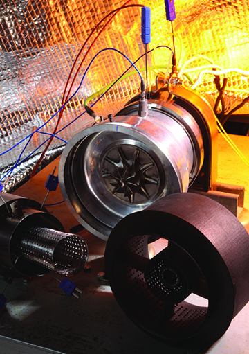
Left: The turbine disk is visible in the prototype’s interior, with the plastic inlet duct in the right foreground.
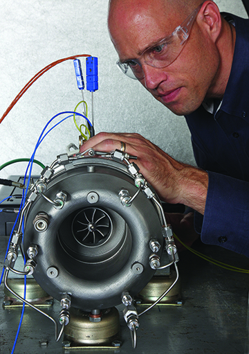
Right: Sensors were fitted to the prototype during testing.
Component fabrication process
The SwRI-designed machine was fabricated using a number of unusual features. The hot section (the stator and combustor portion) was produced using a direct metal laser sintering (DMLS) process that enabled the team to build an intricate part that would typically be developed through the formation and assembly of several formed sheet metal parts. Because this was a prototype, not intended for production, investment in the forming process would have been cost-prohibitive. The DMLS process was critical in enabling the proper combustor design while still being representative of a potential final flight configuration.
The engine inlet duct was made of plastic material using a 3-D printer. Because the duct encounters only relatively cool inlet air, the material strength requirements are low. Meanwhile, 3-D printing enabled the team to easily manufacture the part’s contours and hole pattern without excessive machining or molding costs. The holes in the inlet duct reduce gas turbine inlet noise, and the cavity behind the holes can be filled with sound-absorption materials.
The compressor and turbine are radial configurations made of titanium and Inconel alloy 718, respectively. The SwRI team originally planned to manufacture the turbomachinery wheels using DMLS. However, the only vendor capable of achieving the material strength requirements using DMLS was unavailable for hire. Therefore, the team was required to modify the design such that it could be manufactured using conventional five-axis machining.
Testing the system
The team developed a general test plan and several sub-plans to test subsystems or specific features of the system. The general plan allowed for a cumulative build of the system, checking each sub-system prior to adding the next sub-system. The test plan consists of a multi-phase process designed to evaluate subsystems individually before testing the entire power assembly.
SwRI developed a LabView™-based data acquisition system for monitoring the instrumentation controlling its various systems, including the motor-generator, fuel pump and igniter. In all, four emergency buttons were installed to allow operators to safely shut down the system from numerous locations within the test cell.
Some facility improvements were incorporated at SwRI’s facilities for safe and effective testing, including a containment vessel surrounding the machine to protect from a potential rotor burst event.
Conclusion
The SwRI-developed gas turbine generator was successfully built and partially commissioned during this project. The SwRI team performed some initial machine runs and demonstrated a number of major system milestones.
The combustor was able to ignite at 25 percent of rated machine speed, validating the combustor and air-assist fuel nozzle designs. The mechanical integrity of the turbine and compressor wheels was demonstrated, validating the mechanical design.
The minimal bearing lubrication system worked well, and bearing temperatures and noise were low. The overhung turbine and compressor demonstrated good rotor dynamics, and critical shaft speeds were close to predictions. The softly supported rotor system allowed tuning to meet the machine requirements. In-situ rotor system balancing resulted in very low vibration levels, and the compressor met aerodynamic performance predictions.
The final machine was delivered to the client after testing at SwRI. The completed power system is expected to undergo continued development and testing to prove and possibly expand its capability. With further development the machine could be ideally suited for operation in a hybrid UAV system. In addition, it could be used to develop other new applications for the patented SwRI-developed gas turbine as a power source.
For more information, visit Unmanned Aerial Systems.
This research is based upon work supported by the Office of the Director of National Intelligence (ODNI), Intelligence Advanced Research Projects Activity (IARPA), via USAF/AFRL contract. The views and con-clusions contained herein are those of the authors and should not be interpreted as necessarily representing the official policies or endorsements, either expressed or implied, of ODNI, IARPA, or the U.S. government. The U.S. government is authorized to reproduce and distribute reprints for governmental purposes notwithstanding any copyright annotation thereon.