
By the onset of World War II, militaries around the world depended on radio signal transmissions to communicate with their forces, particularly air and naval assets. Nearly simultaneously, militaries began monitoring the communications of combatants, sometimes to great advantage, playing a key role in World War II’s Battle of the Atlantic. Determining the direction of arrival of enemy combatant communications helped pinpoint their actual location. Direction finding, or DF, was directly or indirectly responsible for 24% of all U-boats sunk by Allied Forces during the war.
Modern-day DF systems are used not only to determine the directions of enemy combatants, but also to locate emergency transponders for search and rescue as well as for situational awareness. By combining the directional information from two or more suitably spaced DF systems, the location of the transmitter can be calculated by triangulation. A key component of naval direction-finding systems is the DF antenna. It consists of one or more arrays of antennas, or elements, and for higher frequencies is distributed around a central mast. The other key component is the processing equipment, which consists of high-end radio receivers and computers.
DETAIL
A transducer is an electronic device that converts energy from one form into another. Antennas are transducers that capture radio signals out of the air and convert them into electrical signals.
Southwest Research Institute was founded just after WWII, and some of the very first internally funded research programs advanced antenna technologies. In the 75 years since, the radio spectrum has become exponentially more crowded, jammed with every conceivable wireless signal, pushing operating frequencies higher and higher. What began in the high-frequency (HF) band during WWII has grown to now include very-high-frequency (VHF), ultra-high-frequency (UHF) and the lower ranges of the super-high-frequency (SHF) bands. SwRI has developed an extensive communications electronic support measures program and is continually looking for novel solutions in this technical arena to pinpoint the source of increasingly sophisticated signals (see infographic in this issue).
Today’s radio signals are increasingly higher in frequency and bandwidth with complex modulations. It is in this environment that a client asked SwRI to extend the upper frequency range of one of its current shipboard DF antenna systems. SwRI had originally designed, fabricated and installed these systems in the 1980s and supported numerous upgrades to them over the years.
ABOUT THE AUTHOR
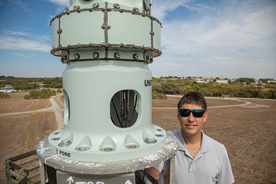
Patrick Siemsen, shown with the cylindrical continuous-slot antenna array being tested atop a 70-foot tower at SwRI’s 200-acre antenna test range, has been developing innovative direction-finding (DF) antenna arrays to support tactical communications intelligence at Southwest Research Institute for over 28 years. He has led the development of a variety of novel DF antennas, among them a body-worn DF antenna vest, a portable DF “tent” antenna and a low-profile, vehicle-mounted distributed DF antenna array. He has also developed low Radar Cross Section (RCS) antennas using conductive composite technology.
Antennas 101
Antennas are transducers that capture arriving radio signals from the air and convert them into electrical signals at its feed, or connection point. The signals are then sent to processing equipment. Conversely, a radio transmitter generates an electrical signal and sends it via an antenna, which converts it into a transmitted radio signal. Radio signals are electromagnetic waves, a combination of magnetic and electric fields that oscillate at a specific frequency, traveling at the speed of light. In an imperfect analogy, radio signals are like waves on a pond emanating out when a stone is dropped, weakening over distance. The distance between peaks or valleys in the wave is the wavelength. The higher the frequency of the radio signal, the smaller the wavelength. Antennas scale to the size of the wavelength, becoming smaller at higher frequencies. Antennas come in many sizes and shapes depending on their intended operating frequency and usage, which can range from shipboard applications to stationary land installments to mobile body-worn systems.

Radio signals, or electromagnetic waves, consist of electric and magnetic fields oscillating together at a specific frequency. A cycle is the pattern of a wave before it repeats itself, while its wavelength is the distance it travels in one cycle. The number of cycles, or times that a wave repeats in a second, is its frequency, which is measured in hertz (Hz). Kilohertz (kHz) is thousands of hertz, megahertz (MHz) is millions, and gigahertz (GHz) is the billions range. The electromagnetic spectrum ranges from 3 kilohertz up to 3,000 gigahertz. Radio signals are generated by a transmitter and detected by a receiver. An antenna allows a radio transmitter to send radio signals across the airwaves and a receiver to analyze these signals. Transmitters and receivers are typically designed to operate over a limited range of frequencies.
In a DF antenna array, the antenna elements are arranged to capture an incoming radio signal at various spatial locations to ultimately determine the direction of arrival. Depending on frequency, traditional DF antenna elements are usually of the dipole or spiral type, which respond to the electric field, or the loop type, which respond to the magnetic field. They are usually oriented for vertical polarization, which refers to the direction of the electric field portion of the electromagnetic wave; most radio signals used for communications are vertically polarized.
Location, Location, Location
Most higher-frequency wireless communications today range from 100 MHz to 10 GHz, requiring a direct line of sight from one antenna to another to establish a link. Due to the curvature of the Earth, the range of a radio signal is proportional to the height of an antenna above ground. On a ship, the ideal location for any antenna is the very top of the mast. From that vantage point, an antenna has the best reception and a clear unobstructed 360° omnidirectional view. As one can imagine, this real estate is very valuable on the high seas.

SwRI’s 200-acre antenna test range includes two 70-foot towers to simulate and evaluate antenna systems on the masts of naval vessels at sea.
Typically, VHF/UHF DF antennas serve as an extension to the mast of the ship, allowing other antennas of higher priority, i.e. navigational and threat-warning capabilities, to be mounted above them. DF antennas include a central mast with elements extended out around it. The higher the frequency of the radio signal, the smaller the wavelength and the closer the element spacing must be to prevent undesired “ripples” in the beamformed antenna patterns, which are the combination of two or more element outputs. These ripples degrade DF performance and reduce sensitivity. Above a certain frequency, this proper electromagnetic spacing is difficult to maintain using traditional DF elements given their physical build and the required diameter of the central mast. In addition, traditional elements experience destructive mutual coupling in their outputs when spaced too close together. When the client asked SwRI to retrofit an existing antenna to extend its upper operating frequency range into the SHF band, the engineering team at first thought it could not be done without a complete redesign of its mast. With no obvious solutions to the problem, the team had to think outside the box.
A literature search unearthed an unorthodox concept for a wide-band antenna array design originally conceived by Harold Wheeler in 1948, which until now was largely theoretical due to practical limitations. In this concept, an infinite two-dimensional array of electrically small dipole elements spaced close to each other would offer beneficial mutual coupling and, as a result, achieve wide-band operational performance from the lowest frequencies to the highest. Upper frequency cutoff is based on how closely spaced the elements are. Such an array of closely spaced elements could conceivably solve the ripple problem, eliminating pattern distortion in a circular array. But how to reduce the idea of an infinite array to a practical solution seemed elusive. Different methods described in the literature proved impractical.
DETAIL
Beamforming technology combines two or more antenna element outputs for a given purpose. For example, traditional DF antenna elements beamform outputs to create the “sine” and “cosine” patterns used to determine direction. In next-generation smart antennas, beamforming is used to “steer” radio signals in a specific direction, as opposed to broadcasting in all directions.
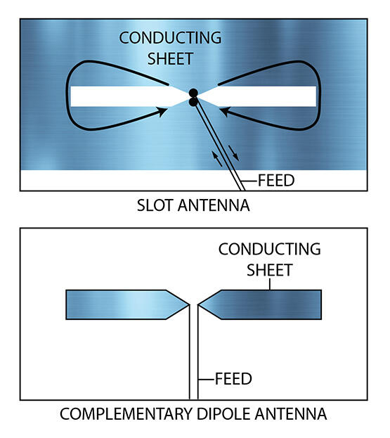
However, one method found in the literature caught the team’s attention: using slot elements in place of dipole elements in Wheeler’s theory. A slot antenna is complementary to a dipole antenna and in its simplest form is just a narrow slot cut out of a conducting sheet and fed from the center. The slots are horizontally oriented for vertically polarized signals, opposite a dipole. Merging electrically small slot antennas long ways, connected end to end, creates a continuous cylindrical slot but with many closely spaced feed points. Multiple slots could then be layered on top of each other. The final product would consist of a cylindrical stack of conductive rings spaced to form slots in between. This design would solve the infinite dimension problem in one dimension but still leave the other dimension and the seemingly insurmountable task of an extremely large number of feeds.

This exploded view of the cylindrical continuous-slot array concept shows three vertically stacked conductive rings spaced away from one another, forming two slots in between having closely spaced feed points. Absorptive material is placed on the inside to prevent interactions with the mast.
The team was nevertheless intrigued by the idea and set out to model such an array using computer-aided design and electromagnetic numerical modeling software. Eventually the team developed an arrangement that achieved the desired frequency bandwidth while requiring only two adjacent continuous slots in the model to be fed. Additional slots above and below were necessary for electrical loading purposes but did not require feeds. Electromagnetic absorbing material placed inside the slots prevents electrical interactions with the antenna mast.
To feed the two slots, the team devised a symmetrical dual-ring corporate feed network using microstrips on the backside of the conductive rings, providing a uniform distribution of up to eight feeds for a single input. This effectively divided the array into sections, or equally spaced DF elements. Each DF element, including its microstrip feeds, could be fabricated on a single printed-circuit board. The array would be fed by a network of 180-degree hybrids — one for each DF element. Individual antenna elements could be constructed separately and then be assembled around an existing mast in a pie-like manner.
The team obtained internal funding to further refine this design, which they referred to as the cylindrical continuous-slot antenna array, and build a proof-of-concept prototype. This prototype was simple in nature, octagonal in shape and had eight flat antenna sides, or DF elements, with 64 total antenna feeds. Any final version would be curved to create cylindrical appearance. Each element was fabricated using 3D printing technology. From this prototype, SwRI validated the numerical modeling and conducted performance analysis, collecting antenna patterns inside an anechoic chamber. Successful validation and encouraging performance gave the team confidence in further electromagnetic numerical modeling to design the final antenna version for the client and apply for a patent.
As the team initiated the final version, they wondered if the array could be designed to mount in an abandoned location in the lower portion of the existing antenna mast. The DF antenna had already been retrofitted once, removing a lower frequency array from the bottom half of the antenna mast, leaving behind a series of sealed bolt holes. It was initially assumed the upper portion of the mast would have to be redesigned to accommodate the new array. Taking advantage of this unused real estate at the bottom portion of a mast would eliminate the need for a complete redesign of the entire upper half of the antenna. A mast redesign would have been an expensive endeavor, considering all the design, fabrication and testing involved.
DETAIL
A slot antenna is the complement to the dipole antenna. If a dipole antenna is cut out of a conducting sheet, the remaining material makes a slot antenna, fed across the center.
Because the bottom portion of a mast is wider in diameter, the number of antenna feeds would have to increase significantly, a rather intimidating endeavor. However, the successful numerical modeling after the prototype validation allowed the design to move forward without a hitch. The final version consisted of eight antenna elements that individually mated to the existing bolt-hole pattern on the antenna mast. The elements came together like a puzzle, creating the appearance of one continuous curved antenna around the mast with 128 total antenna feeds. The resulting antenna patterns and DF performance were exceptional, solving the ripple problem that plagued previous higher-frequency designs.
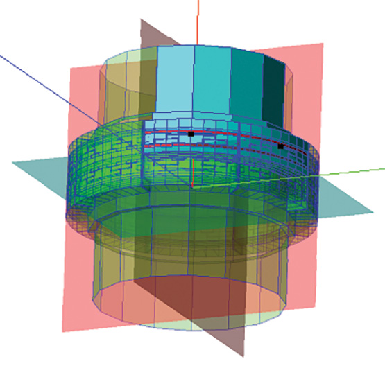
Using computer-aided design and electromagnetic numerical modeling software, SwRI was able to successfully design and predict the performance of the cylindrical slot antenna array before the first piece of metal was cut.
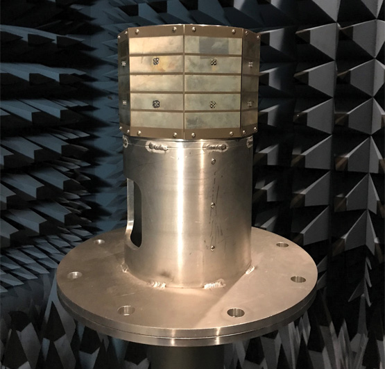
SwRI prototyped the initial design and evaluated its performance in an anechoic chamber and through computer modeling.
The first retrofitted antenna with the new array was deployed late last year with positive results. Currently, SwRI is under contract to retrofit additional ships over the next several years. In addition to the antenna, the team is updating the below-deck processing equipment with wider bandwidth receivers and next-generation processing capabilities, using SwRI’s Frontier software architecture. The client also plans to provide these advanced capabilities to its next generation of warships.
As this novel antenna illustrates, SwRI remains on the vanguard in developing the latest state-of-the-art antenna technology. Moving forward, the SwRI team plans to utilize a version of this patented slot array in future higher-frequency designs. Other applications of the slot array are under investigation, including airborne and land-based systems. Its lightweight conformal design could also support clandestine law enforcement operations. SwRI is also exploring dual-polarized versions as a research initiative and a reduced-channel version using innovative beamformer combinations for N-channel DF and advanced DF processing with antenna steering algorithms.
For the final design, the elements individually mated to the bolt-hole pattern on the existing antenna mast abandoned after a previous retrofit. The elements came together seamlessly, creating the appearance of a continuous, conformal antenna. Radomes covered each element for environmental protection.

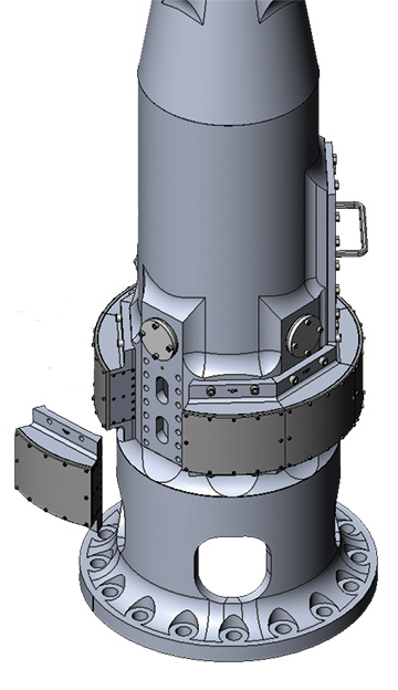
SwRI engineers designed the cylindrical slot array to fit near the base of this shipboard antenna to take advantage of existing unused space, extending the operating frequency range of the antenna while avoiding an expensive redesign of the upper mast.
Questions about this story or Tactical Products? Contact Patrick Siemsen at +1 720 208 7209.