For 30 years, NASA flew a fleet of five space shuttles on 135 missions. From 1981–2011, these partially reusable low Earth orbital spacecraft systems launched from the Kennedy Space Center (KSC) in Florida. Prior to launch, each shuttle was strapped to two solid rocket boosters and an orange fuel tank towering over the boosters and the shuttle itself on the launchpad. This massive fuel tank housed the cryogenic fuel and oxidizer the shuttle engines used during launch. All launch vehicles, including the shuttle, require a tremendous amount of fuel to break free of gravity and enter Earth orbit. As payload mass increases, more fuel is required to launch. This presents a cyclic dilemma. The more fuel needed to lift a heavier payload, the more fuel needed to compensate for the fuel’s added mass.
DETAIL
Cryogenic fuels are typically liquefied gases stored at extremely low temperatures to maintain a liquid state. Space applications require both fuel and oxidizer propellants because the oxygen needed for combustion of ordinary fuels is virtually nonexistent in the vacuum of space. Liquid fuels combusted with oxygen offer high propulsion performance at relatively low cost compared to other fuel options.
Rockets are the only vehicles where the fuel tank dwarfs the payload itself. The fuel, also called propellant, usually makes up more than 80% of the total launch vehicle mass. With so much of the mass dictated by a liquid, it is easy to imagine that any movement of the propellant can have drastic effects on vehicle trajectory. Inside the fuel tank, propellant can slosh back and forth much like a cup of coffee as you drive down the road. When most of a vehicle’s mass is subject to this sloshing, the guidance, navigation and control (GNC) rocket systems must accommodate these effects while maintaining vehicle trajectory.
In the first few decades of the space program, Southwest Research Institute established itself as a world leader in the experimental investigation and analysis of propellant dynamics effects in spacecraft tanks. The Institute had its first program in this area in the 1950s before the National Aeronautics and Space Administration (NASA) was even established. This project studied the motion of liquid fuel when rocket thrust terminated. Since then, hundreds of millions of dollars in research and development activities have continued, with hundreds of programs applied to dozens of individual spacecraft and rockets. The research addressed two related but distinct propellant dynamics problems associated with launch vehicles blasting off from Earth’s surface and spinning spacecraft in orbit or traveling through space. The Institute continues its strong program in propellant dynamics to support the emerging commercial space industry as well as new government initiatives.
About the Author
Grant Musgrove manages the Propulsion and Energy Machinery Section in SwRI’s Mechanical Engineering Division. He specializes in thermal-fluid dynamics, heat transfer and propulsion systems, particularly using experimental and computational methods in rotating machinery applications.

Slosh and Spin Testing
Using scale models of tanks and novel spin test facilities, SwRI played a critical role running experiments to create some of the copious amounts of data initially needed to develop simple models for the wide range of tank designs under investigation. Early in the space program, slosh motion had to be predictable without the benefit of computer simulations.
Engineers then developed models using a mechanical system — approximated as either a swinging pendulum or an oscillating mass-spring system — to represent the liquid sloshing motion. Compensating for differences in tank shape, internal features and fill levels required extensive test data to calibrate the models. Guidance, navigation and control (GNC) specialists still use these simple models today for system development for quick turnaround vehicle trajectory calculations.
In addition to fuel sloshing back-and-forth in tanks, a vehicle propellant system presents additional challenges and concerns, such as tank pressurization, propellant distribution and “pogo.” Pogo is described as the self-excited longitudinal oscillations in space launch vehicles — so named because the phenomenon vibrates the rocket up and down in a manner similar to bouncing on a pogo stick. While pogo events are usually short-lived, they can still damage the payload or the vehicle depending on acceleration levels achieved during the unstable interaction. For example, pogo was responsible for the center engine cutoff during liftoff of Apollo 13.
Propellant distribution in the storage tank is critical to operations. The tank sump feeds the engine fuel during operations. At liftoff, gravity keeps the propellant in contact with the sump. For space maneuvers and landing, though, zero gravity allows the liquid in a fuel tank to form a blob in a random location, requiring precautions be made to ensure the fuel pump can draw fuel.
Fluid spin-up in large spacecraft fuel tanks can significantly affect vehicle stability. SwRI evaluated the DAWN spacecraft’s fuel tank to measure transient effects using a surrogate fluid to simulate the actual propellant. The test results enhanced the launch vehicle stability control system and contributed to slosh modeling efforts.

SwRI evaluates the effects of fluid motion in spacecraft propellant tanks, such as this full-scale model of a tank with a damping internal diaphragm used on the New Horizons and Deep Impact spacecraft. Our engineers design test tanks to match closely the internal design features of spacecraft tanks, while providing access for sensors and allowing visual observations.

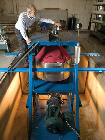
Retiree Dr. Franklin Dodge holds one of the tanks used in SwRI’s liquid motion experiment conducted onboard the space shuttle in 1997. The scale-model experiment led to the development of a full-scale spinning slosh test facility.
Engineers continue to develop reduced order models (ROMs) — simplifications of high-fidelity, complex models — to understand propellant behavior and its effects in GNC simulations to quickly study a system’s dominant effects using minimal computational resources. More recently, SwRI has been applying modern analysis methods to this old problem as well as other propellant system considerations.
Slosh Modeling
Using computational fluid dynamics (CFD), engineers can better understand the effects that specific flight dynamics and tank configurations have on liquid motion. CFD predicts parameters, requiring less slosh testing to verify that new tank designs and internal structures suppress liquid sloshing. The result is accelerated advances in tank design at reduced cost. For example, CFD simulations can estimate the model inputs, such as frequency and damping ratio, needed for GNC simulations. CFD simulates the performance of propellant sloshing mitigation approaches and has become indispensable for evaluating new tank designs while minimizing costly testing.
DETAIL
Computational fluid dynamics is the science of numerically solving fluid motion equations to produce quantitative predictions and/or analyses of fluid flow phenomena.
These new modeling methods are also useful for estimating the distribution of propellant in the tanks. Today’s launch vehicles no longer use expendable single-use tanks. Instead, these very large reusable tanks now return to Earth, landing with very small amounts of propellant inside. In this situation, as well as air-launched vehicles, the vehicle experiences a near zero-g freefall state for a period of time, allowing the propellant to move freely throughout the tank. This means there is no guarantee that the liquid propellant will be present at the tank sump when the engines need to be started. CFD simulations can model the propellant movement in the tank during the vehicle freefall to help the vehicle designers provide for the propellant to be at the bottom of the tank when the engines need to start. Otherwise, the engines will ingest vapor instead of liquid fuel, which could cause a catastrophic landing.
Software Solutions
Engineers are also applying other software modeling approaches to propellant system development. For instance, boil-off gas in cryogenic tanks occurs when heat transfer raises the temperature of the liquid, allowing small amounts of it to return to its vapor phase. This evaporation raises the pressure inside the cryogenic tank during storage and transportation and must be vented overboard to maintain acceptable temperatures and pressures. In addition, a pressurant gas is typically added to the tanks during engine operation to keep pressures from dropping too low. Managing this complex thermodynamic and heat transfer problem often requires a separate pressurization system. SwRI uses software to model this thermodynamic system throughout the vehicle flight plan, assessing how various trajectories with different flight times and Sun exposure could contribute to boil-off and pressurant gas requirements. The large number of conditions evaluated improve confidence in the design and reduce the number of needlessly conservative assumptions.
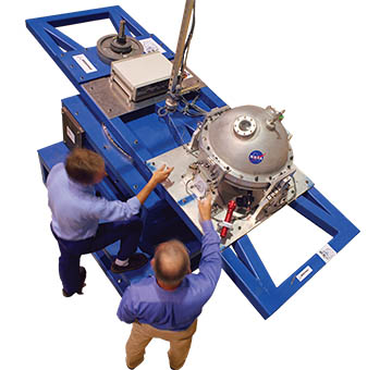
In the early 2000s, SwRI established a Spinning Slosh Test Rig (SSTR) to test fluid dynamic effects in full-scale models of spacecraft fuel tanks. Engineers tested this tank from the Genesis spacecraft to ensure that the spacecraft will remain stable during orbit insertion.
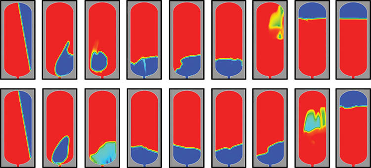
SwRI uses CFD simulations to analyze fluid motions in an air-launched rocket. The images illustrate how the liquid (red) and the vapor (blue) move around the tank in respect to the outlet.
Additionally, a tank’s feedline, the critical path from the tank to the engine, can affect pump operations. Feedline pipes are designed to be as compact as possible to save weight and, as such, include twists and turns between the tank and the engines that can contribute to pressure loss and flow distribution problems. CFD modeling of these systems is critical because there is no available test data to understand how closely coupled twists and turns in the feedline affect overall system performance. The feedline is connected to both the vehicle structure and the engines, creating a feedback loop between structural vibrations and engine thrust fluctuations, also called pogo. With simulation capabilities, a wide range of operational scenarios can be investigated quickly as the vehicle development progresses to avoid or mitigate pogo. Engineers can also use CFD to evaluate and adjust mitigation scenarios based on their performance over a wide range of operating conditions.
Tomorrow's Launch Technology
Using today’s modern simulation capabilities, tomorrow’s launch vehicles can be designed in less time and at lower cost than 40 years ago. Much more analysis can be done during design, and many more operational scenarios can be investigated. Modern modeling reduces risks by asking “what if?” and assessing the likelihood and impact of a particular scenario. The detailed models make higher confidence predictions, which lead to less conservative assumptions and more realistic requirements. Forty years ago, for example, only a handful of cases could be modeled with limited assumptions. The worst case was often used to direct vehicle requirements with additional safety margins. Now, detailed models can identify arcane worst-case scenarios and evaluate the likelihood and impact on vehicle design. At SwRI, we realize and emphasize that using these simulations for launch vehicle development is made possible by the decades of experience and test data compiled in the past. These data and the expertise that goes with them are critical to ensuring the modeling work is accurate.
Most of the earliest generation of propellant dynamics engineers have retired, and many next-generation launch vehicles are being developed by the emerging commercial space industry. Without transitioning this information to a new generation of engineers, decades of experience learned throughout the space program would be lost. SwRI is committed to passing this knowledge along through training and technology transfer.
Questions about liquid propulsion? Contact Tim Allison or call +1 210 522 3561.
This IS Rocket Science!
Learn about launch vehicle liquid propellant system design and analysis
SwRI is offering a launch vehicle propulsion short course for participants with an engineering background. Attendees will develop an understanding of the propellant system needed to support the design, test and operation of launch vehicles, including in-depth understanding of liquid propellant dynamics and how they affect launch vehicle design. The course covers liquid propellant slosh concepts and how to use analytical, computational and experimental methods to characterize slosh parameters for guidance, navigation and control simulations.
• Propellant Tanks • Pressurization Systems • Slosh Baffling • Feedline Dynamics • Start Slump • Water Hammer • Pogo • Propellant Modeling • Cryogenics • Computational Fluid Dynamics • Phase Change • Thermodynamics • Boil-Off Prevention
To register, contact Tim Allison or call +1 210 522 3561.