
Background
Electric vehicles (EVs) continue to gain market share globally. The most common architecture for EV traction motors is the interior permanent-magnet synchronous machine (IPMSM), which offers high power density and high efficiency when constructed with rare-earth magnets. The expensive rare-earth minerals used in these magnets are sourced mostly from China and are subject to pricing shocks, tariffs, and geopolitical supply-chain problems. Additionally, there’s insufficient supply of these minerals for the entire transportation sector to switch from internal-combustion engines to IPMSMs with rare-earth magnets. The electrically excited synchronous machine (EESM) is gaining market share due to its magnet-free design and its IPSM-rivaling power density and efficiency. Additionally, is not a concern, because demagnetization EESMs can operate at considerably higher temperatures (>200 °C) than IPMSMs (~100-120 °C). The objective of this project is to test our hypotheses that (a) the higher thermal of an EESM will allow an IPMSM to be downsized while still providing comparable short-duration power and (b) this change will increase efficiency and thus range while reducing total magnet and copper cost.
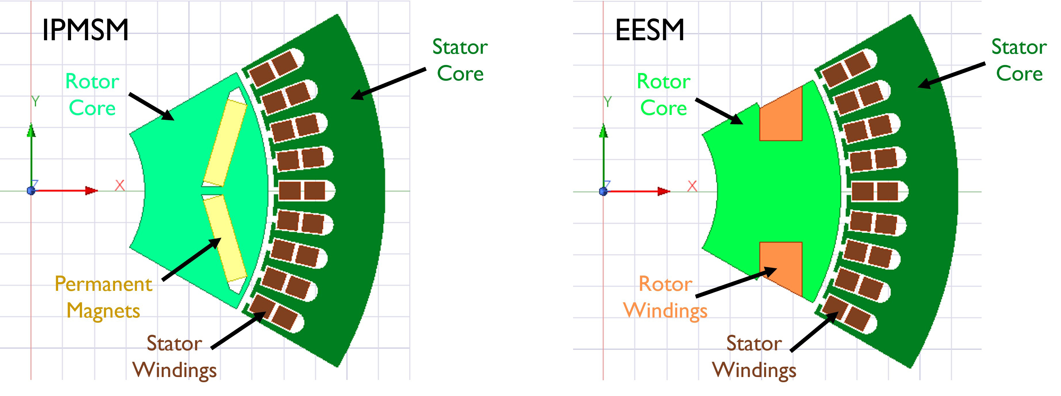
Figure 1: 2D models of the IPMSM and initial EESM design illustrate how the two architectures differ. The motors’ symmetry allows only 1/6 of each to be modeled to reduce simulation time.
Approach
Our approach is simulation-based but is informed by our extensive testing experience and test data. We created 2D motor models—see Figure 1—of the Tesla Model 3 rear motor (an IPMSM) and a new EESM design with the same rotor diameter, stator length, and stator. We are using simulations of these models to determine flux-linkage maps and maximum torque per ampere (MTPA) calibrations for these motors. We’ve also created a 3D model—see Figure 2—of the same IPMSM. This model couples three Ansys software packages to capture all the physics present in the machine: Maxwell for electromagnetics, Mechanical for solid conduction, and Fluent for fluid convection. Coupling is done via Ansys Workbench with Mechanical as the central system. We will create a corresponding model of the initial IPSMS design and use both models to simulate efficiency maps and then evaluate the models’ short-duration power using the sustained power defined in SAE J2908, imposing different temperature limits based on our testing of IPMSMs and EESMs. We’ll then iterate the EESM design, downsizing it until the motor achieves the same sustained power as the IPMSM.
Accomplishments
We’ve built a 1D vehicle model of the Tesla Model 3 that we will use to simulate the vehicle, as powered by the IPMSM and the final EESM, operating over the range test defined in SAE J1634. We will then compare the simulated ranges and estimate and compare the total magnet and copper cost in the final designs.
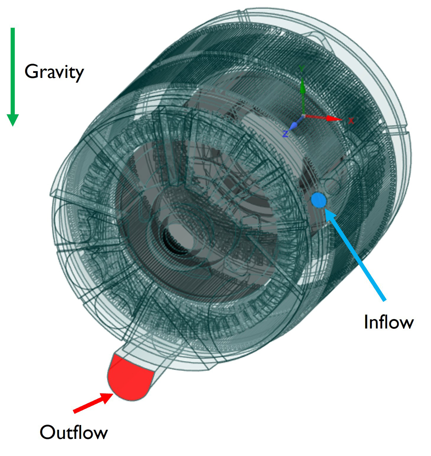
Figure 2: A 3D model of the IPMSM shows its internal structure.