
Background
Predicting crack growth in metallic components has important applications in aircraft sustainment and engine rotor risk assessment. A critical aspect of fatigue life prediction is the calculation of stress intensity factors (SIFs) for a given crack geometry. These SIF values are combined with material models, such as Paris Law, to predict the rate of crack propagation in metallic components.
Direct computational modeling of cracks in 3D component geometries has proven to be both computationally expensive and cumbersome. For example, a meshed turbine blade, such as the one shown in Figure 1, can contain hundreds of thousands of elements that need to be re-meshed when a crack is introduced. Even in the case of a simple semi-circular crack in a plate, crack-conforming meshes must be developed. Idealizing a crack model into simplified geometry allows for the pre-computation of weight functions, which can then be combined with component stresses to compute SIFs. However, this approach leads to approximations in fatigue crack growth life predictions and can also complicate comparisons with experimental data.
Approach
This project aims to develop a methodology for computing SIF values that is user-friendly, robust in its results, and does not intrusively alter the 3D component computational model. A commercial finite element analysis (FEA) program is employed to compute stresses and strains. To avoid cumbersome process of remeshing to model cracks, this tool is coupled with a boundary element (BE) analysis program, which does not require remeshing the volume. The coupled software programs iteratively analyze the global component and a local region to compute SIFs. Displacements from the global FEA model are applied to the BE model. In turn, tractions from the BE model are applied back to the global model as corrective nodal forces. Iterations continue until interface displacements converge for the combined FE-BE model.
Accomplishments
The method was implemented as a driver program that interfaces with both the BE library routines and a commercial FEA program. It underwent rigorous code and solution verification to ensure correctness of the implementation. For verification, a simple rectangular plate with a semi-circular surface crack was chosen as a test case. Python scripts were developed to automate the extraction of element faces from the 3D FEA model and to generate a BE model input file. The crack geometry is automatically created and meshed within the FEA preprocessor.
Solution verification was conducted using a pre-existing database of reference crack solutions for a surface crack in a rectangular plate. Results indicated good agreement (< 5% error) in 8 out of 12 SIF values in cases where the solution converged, moderate differences (between 5% and 15%) for 2 out of 12 SIF values, and relatively large differences (>15%) for 2 out of 12 SIF values.
For the chosen demonstration example, the geometry included many filleted regions that were difficult to mesh once a crack was introduced. A relatively flat surface was therefore selected as the crack location. The turbine blade was subjected to both centrifugal and bending loads. The final FEA model containing the crack had more than five times as many nodes as the combined FE-BE model, demonstrating the economy of the approach. A comparison of FEA results with iterative global local (IGL) method, showed very similar trends along the crack front, except in the region where the crack front meets the free surface, as shown in Figure 2. The peak SIF value was underpredicted by about 13%.
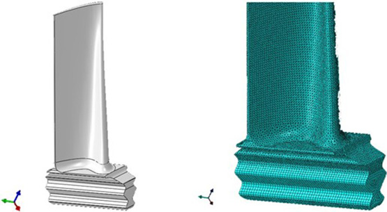
Figure 1: Turbine blade CAD geometry and corresponding mesh near blade root.
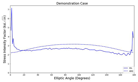
Figure 2: Comparison of FEA results and FE-BE iteration results.
Publications
A joint paper by the principal investigator and project associate Matthew Kirby will be submitted to an archival journal, such as ASME Journal of Engineering for Gas Turbines and Power.
Presentations
An abstract will be submitted to ASME Turbo Expo 2026 conference. If accepted it will be presented at the conference in June 2026.