
Background
A novel machine (patent #US12416301B2) uses a sinusoidal traveling wave along a membrane to impart energy to a fluid in the wave’s travel direction. The membrane is contained within a channel, and thus, the propagation of the transverse wave can add both velocity and pressure to the fluid. As compared to other pumps and compressors, the machine described herein has fewer moving parts and points of failure than a reciprocating machine, has less exacting machining tolerances and better resistance to wear than progressive cavity or gerotor pumps, has higher pressure capabilities than peristaltic pumps, and lower material velocities than axial or centrifugal machines. Because fluid speed through the channel will be based on the propagation speed of the traveling wave, exit velocities can be made very high and allow for significant amounts of thrust from a small amount of material. Unlike an air propeller, which takes a significant amount of time to accelerate to full speed or to change speed, this concept can start producing flow within milliseconds and respond rapidly to changing demand. For quad-rotor electric aircraft, this could provide improved safety, reliability, and performance as a propeller alternative. The lack of high-speed rotating blades also means the risk to nearby personnel is greatly reduced, which could allow for use in tighter urban environments. Because multiple membrane channels can be stacked in parallel, there could be improved reliability and safety versus bladed propulsion devices, as one failed membrane would not necessarily result in a catastrophic failure of the propulsion unit or risk damaging other parts of the aircraft. Stacks of channels, with a flat and rectangular form factor, could even be incorporated into the wing structure of a more traditional aircraft, lending VTOL capability without adding to the wing cross-sectional area during horizontal flight. In underwater propulsion, the concept is likely to have reduced operating noise, and like the knifefish, flow direction and thrust can be almost instantly reversed. In microfluidic applications, it could act as a simple and compact piezo-driven pump with no valves, greatly simplifying the design and operation of a microfluidic device. In a gas boosting application, the concept would easily allow for a hermetically sealed, high-inlet pressure device with significantly reduced air consumption and improved reliability versus its competitors.
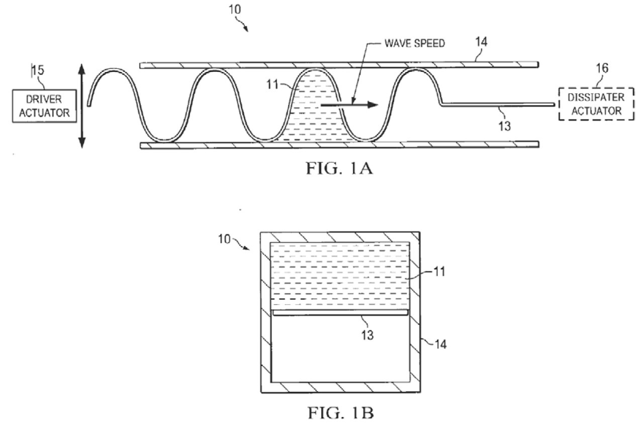
Figure 1: Conceptual illustration of operating principle.
Approach
This project seeks to quantify the flow and pressure performance of the traveling wave flow machine by, first, collecting and utilizing data from the previously constructed prototype to develop analytical and CFD models to predict performance and then utilizing these models to design a prototype capable of industry-relevant performance. Figure 1 shows the original proof-of-concept prototype that demonstrated the ability of the concept to produce flow. Figure 2 shows how pressure, temperature, and flow measurements were proposed to quantify performance of the prototype.
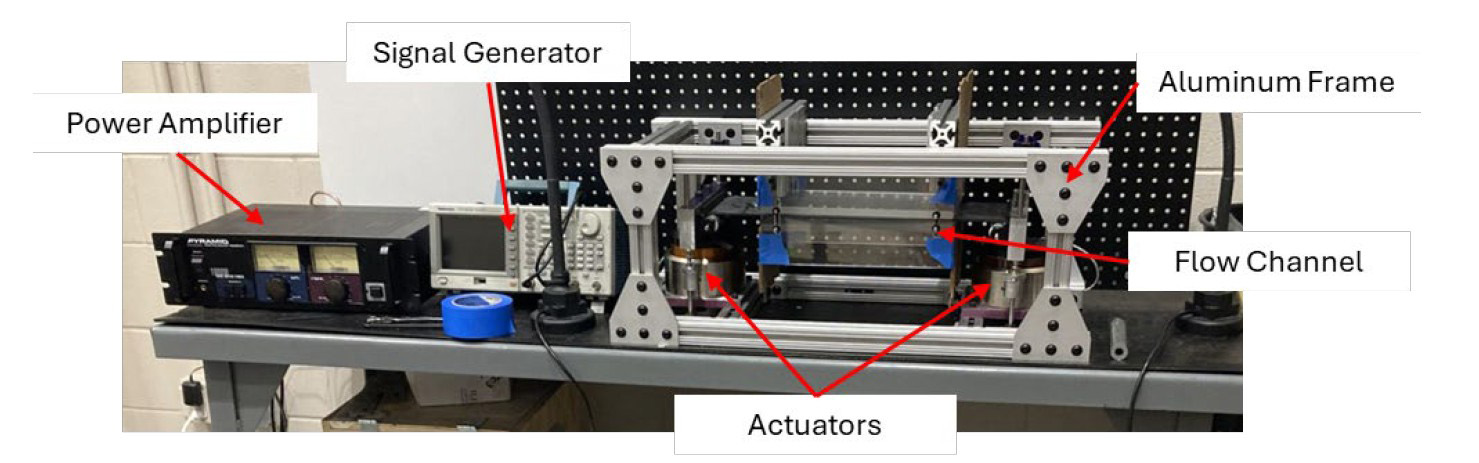
Figure 2: Original proof-of-concept prototype from previous exploratory IR&D.
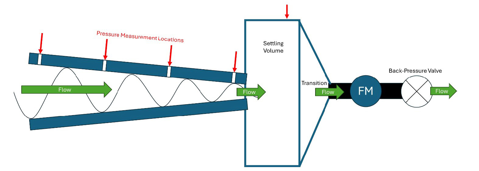
Figure 3: Conceptual schematic showing proposed instrument locations and performance test set up.
Accomplishments
The prototype rig was successfully instrumented, commissioned, and operated. Performance data has been collected and is currently being used to analyze performance and tune models. Data was collected for a range of operating frequencies, channel heights, and angles of channel convergence. The CFD study is underway and has completed its turbulence model selection and mesh convergence study. The CFD study utilizes dynamic mesh refinement and moving mesh boundaries to capture the transient motion and effects of the traveling wave in the membrane. Future CFD efforts will emulate the test geometry and operation as closely as possible, and later, the conceptual performance prototype design. Design sweeps and conceptual design of a performance prototype will be performed as the project concludes this year.
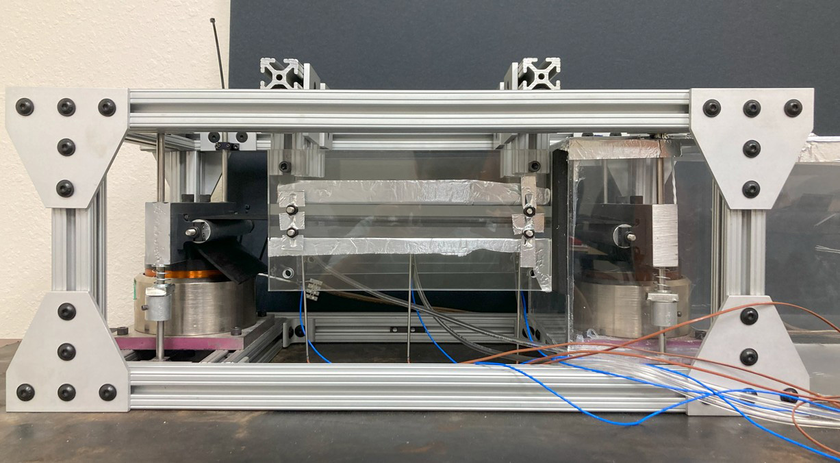
Figure 4: Existing prototype with instrumentation installed.
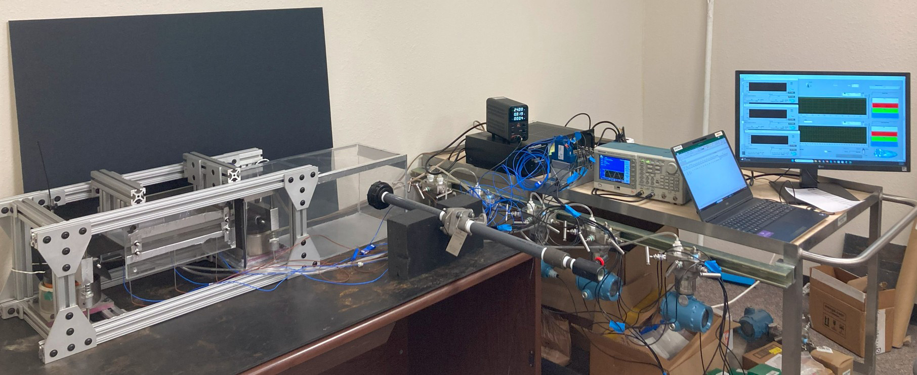
Figure 5: Test set up with settling volume, power electronics, and data acquisition ready for performance testing.
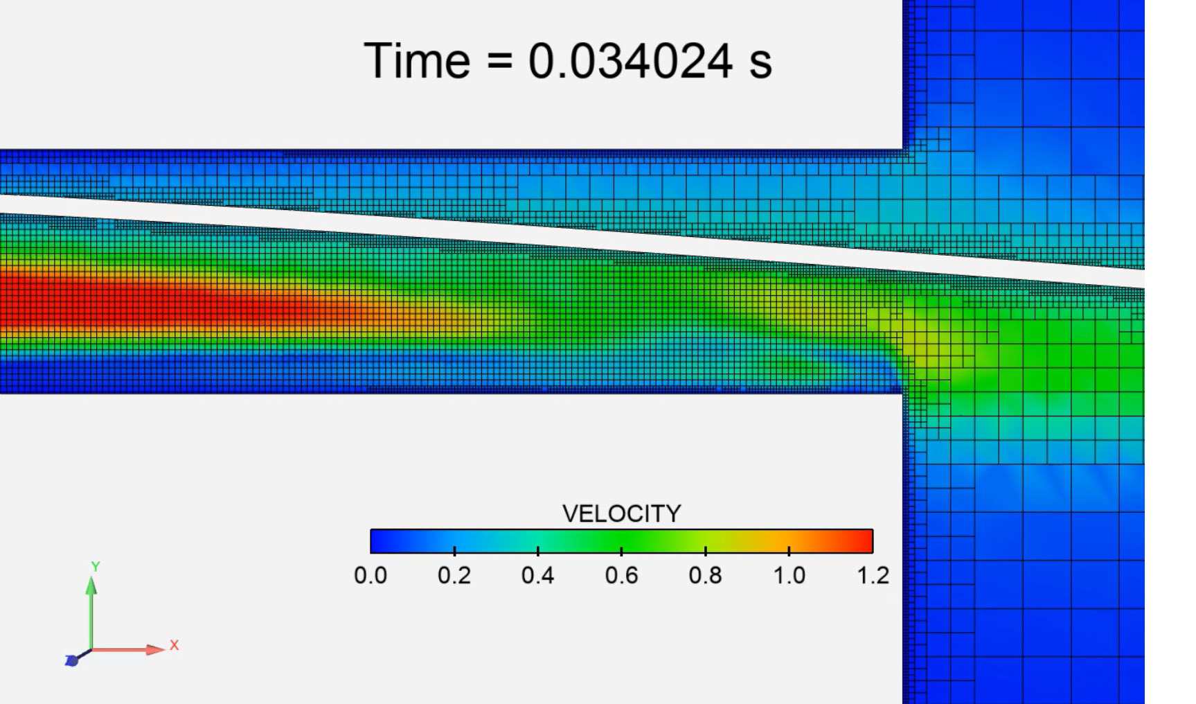
Figure 6: Preliminary CFD result showing the channel outlet during startup.
Patents
Nolen, Craig R., Jr. “Traveling Wave Fluid Energy Machine.” US12416301B2, September 16, 2025.