
Background
Slosh baffles are designed to reduce the energy of the fluid motion in a propellant tank for better control of the vehicle. Oftentimes, the baffles are not welded directly to the inner diameter of the tank but rely on a fixture with discrete mounting locations to hold them in place. Such a fixture results in a gap between the tank wall and the outer diameter of the baffle. The impact of this gap on the damping effectiveness of the baffle is not well documented in open literature. To enhance the existing data set and our own design capabilities, the team conducted a test campaign exploring the effect of baffle gaps on slosh damping.
Approach
The objective of the project was to conduct experiments to determine the effect of baffle wall-gaps on slosh damping performance. The tested baffles are detailed in Figure 1. The slosh tests were conducted in an already-built cylindrical tank on top of a shaker table. Each baffle geometry was tested at a range of liquid fill levels. At each fill level, the shaker table was moved with a sinusoidal motion until the desired slosh amplitude was achieved. The table motion was stopped and the liquid motion was observed as it returned to quiescent conditions. Force sensors on the test stand recorded the lateral force and rocking moment loads on the tank. Damping provided by the baffle is calculated from the decay of the force or moment loads.
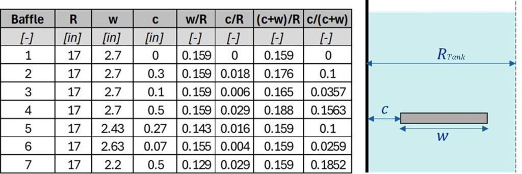
Figure 1: Baffle Geometries Testing with Varying Wall Gaps and Baffle Widths.
Accomplishments
Over the course of the project, the team designed and fabricated a set of baffle geometries to explore the effect of baffle gaps on slosh damping. A total of 287 slosh tests were conducted at various liquid fill heights to generate the data set for damping effectiveness comparisons. Two comparison sets were generated: baffle geometries with the same baffle width ratio of w/Rtank=0.159 and baffle geometries with similar blockage ratios. Both comparisons support the same conclusion. At the fill level of peak damping, the baffle with no gap outperforms the baffles with gaps. However, at most other baffle submergences, a gap 3% of the baffle width has improved damping compared to the no gap case and a gap 11% of the baffle width has comparable damping to the no gap case. These findings corroborate the rule of thumb recommendation that the wall gap be less than 10% of the baffle width but now supply context and additional data for future analysis on baffle sizing projects.
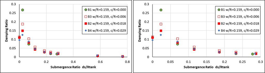
Figure 2: Damping Ratios for Baffles with a Width Ratio of w/Rtank=0.159.
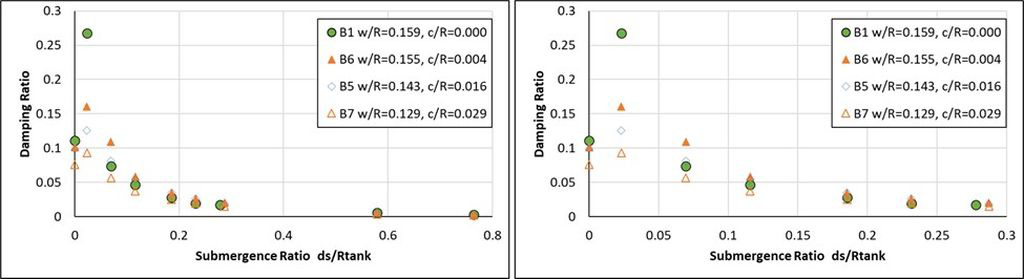
Figure 3: Damping Ratios for Baffles with a Gap and Width Ratio of (c+w)/Rtank=0.159.