Background
The automotive industry is investing billions of dollars in electrification, and SwRI is working to extend its expertise in precision efficiency testing of internal combustion engines to electric machines. Efficiency testing can be conducted using a vehicle mounted on a chassis dynamometer, but more precise results are obtainable by removing the drive unit (motor, gear reduction and differential in a single housing) and operating it on a motor dynamometer. Unfortunately, without inputs from the rest of the vehicle, the stock inverter will not run the drive unit. Additionally, we hypothesize that it is possible to improve the efficiency of a motor by optimizing the control parameters, which are all determined by the inverter. This project therefore has two goals:
-
Demonstrate the ability to operate an ex-vehicle drive unit on a dynamometer by duplicating the stock control strategy on a programmable (usually called “open”) inverter.
-
Explore advanced motor-control techniques to improve the motor’s efficiency.
Approach
This project consists of three phases:
-
Benchmark the efficiency of an electric vehicle. Reverse-engineer the stock control strategy.
-
Characterize the efficiency of an ex-vehicle drive unit operated by an open inverter that has been programmed with the stock control strategy.
-
Measure the effect on the drive unit’s efficiency of advanced control techniques
Accomplishments
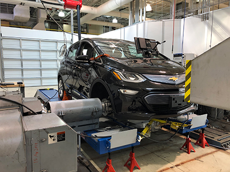
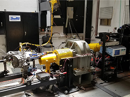
We completed Phase 1 using a Chevrolet Bolt mounted on a hub dynamometer, which measures torque at the wheel hubs, without tire slip, as shown in Figure 1. The data obtained included the inverter’s pulse-width-modulation (PWM) strategy, the switching frequency, the motor speed at which the inverter switches from PWM to fullwave mode, the electrical efficiency of the inverter, the electromechanical efficiency of the drive unit and numerous controller-area network (CAN) signals. The Bolt drive unit was reallocated to an urgent customer project, so we completed Phase 2 using a Tesla Model 3 drive unit, as shown in Figure 2. (The Model 3 and Bolt both use permanent-magnet synchronous motors, so their control strategies are very similar.) We demonstrated reliable, repeatable control of the Model 3 drive unit over much of the stock speed/torque envelope. We will complete Phase 3 by applying advanced control techniques, such as dynamic switching frequency, to the same Model 3 drive unit.

Figure 1: Chevrolet Bolt mounted on the hub dynamometer, which measures speed and torque directly at the wheel hubs.

Figure 2: Tesla Model 3 drive unit mounted to a gearbox and dynamometer in a test cell configured for electric machines.

