
Background
During the 2017 winter storm season in California, Lake Oroville received record inflows and the unlined emergency spillway was used to pass flood water for the first time since the dam was constructed nearly 50 years ago. As a result, portions of the natural terrain of the emergency spillway eroded rapidly and head cutting (backward erosion) came dangerously close to undermining the concrete weir, which if breached could have resulted in the release of a large flood wave (Figure 1). The incident at Oroville, which prompted evacuation of many people from along the Feather River, exposed the vulnerability of unlined emergency spillways for many dams in the U.S. and worldwide because most of these spillways have never been used or tested. Erosion initiated by localized scour on the spillway surface grows as a result of positive feedback between local hydraulic forces at the scour and material response interaction, causing downward or vertical erosion followed by retrograde head cutting towards the reservoir. Modeling this dynamic process of erosion requires a simulation approach for understanding the failure modes and developing an engineering solution to mitigate the problem.

Figure 1: (Left) Oroville Dam spillway erosion showing backward head-cutting on the emergency spillway moving toward the concrete weir (FERC Independent Forensic Team Report Oroville Dam Spillway Incident, 2018).
Figure 2: (Right) Simplified 3D model of the spillway. Model shows the ogee section and hypothetical erodible zone.
Approach
Modeling erosion of soil or rock in spillways requires determination of the erosive power of the fluid flow and the resistive capacity of the geologic medium. SwRI developed a coupled 3D fluid-structure interaction model for simulating the erosion process. The hydraulic loading or erosive power was simulated using computational fluid dynamics (CFD) modeling and the resistive capacity of the geologic medium was modeled using an established empirical approach. CFD calculates flow velocities and shear stresses on the surface of the unlined spillways using an implicit time marching scheme for the solution process. The empirical model was implemented in the CFD code using user defined functions that calculate the erosion depth at every time step. Erosion progression is modeled using dynamic meshing and mesh deformation algorithms. The approach captures the highly coupled hydrodynamic process of erosion where flow alters the shape of the soil bed while the scour depth and shape in turn changes the flow regime.
Accomplishments
The project achieved the objective of developing a proof-of-concept method to model erosion initiation and progression for a simplified 3D spillway geometry (Figure 2). The methodology was used to model an unlined spillway using an idealized 3D geometry, where water overtopping a concrete ogee spillway flows discharges to an unlined spillway that includes a localized highly erodible zone. The simulation process demonstrated initiation and progression of erosion in the erodible zone. As shown in one example with a knickpoint (Figure 3), erosion progresses backwards from the upstream to the downstream with time. This is because the flow accelerates at the upstream edge where it plunges into the knickpoint; hence, the erosion is maximum there. The erosion will continue until the rock layer beneath the erodible surface is reached, indicated by red in the contour scale. The flow regime then causes the erosion to move toward the downstream edge of the knickpoint.
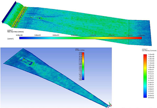
Figure 3: CFD simulation coupled with empirical erosion model results showing: wall shear stress on spillway surface (top) and erosion depth over erodible zone (bottom).