Background
The basic properties of impact craters on planetary surfaces are important for understanding how they formed and the impact event that created them. Almost all past researchers measure impact crater diameters through numerous different methods, including two opposite points (a chord) and a three-point definition. Whenever one reduces a feature to three parameters (center latitude, center longitude, and diameter), information is lost. An ellipse increases the number of parameters to describe the feature and thus provides more information (center latitude, center longitude, major axis, minor axis, and tilt of the major axis relative to a direction such as East-West).
My method of identifying impact craters – tracing crater rims – provides many more points along the rim from which a circle or an ellipse could be fit. In the past, researchers have tended to only measure ellipse properties of craters that visibly “look” elliptical as opposed to circular. My work is really the first to provide ellipse properties for all craters cataloged rather than just “obviously” elliptical craters.
However, statistical tests have revealed that there are biases in the ellipse fits. It would take significantly more manual time to be pixel-perfect in measuring impact craters, and with over 3 million measured on various solar system bodies, it is not practical to manually redo everything. Additionally, with better data, the rims would need to be redone to be again pixel-perfect. Ergo, the concept of the first automated tool to be developed in this work was to create computer code that would take my manual rim traces, an image, and effectively “snap” the manual points to a pixel-perfect location on the crater rim based on sun-facing highlights and anti-sun shadows. This better accuracy would allow more accurate ellipse fits and hence more accurate information about the craters, improving reliability and attractiveness of the product to future funding applications.
The second component of this work was to implement a new technique in the literature to use shadows cast within impact craters to calculate crater depths. While depth usually requires topography information, shadows and basic geometry can also be used. The new technique in the literature (Chappelow et al., 2013) is a much more robust method for using shadows and removes severe limitations of previous methods. A key component of the method is to fit an ellipse to the shadow cast into the crater cavity by the crater rim.
Approach
The approach to this work effort’s second investigation was straightforward and simply involved programming in the appropriate equations, though it included fitting ellipses which was relevant to the first component. The approach to this work effort’s first investigation was guided based on principles of how crater rims are identified by the human eye, such as how shadows are cast based on slopes and sun angles, and that rims must be continuous (as in, cannot jump from one pixel location to another point many pixels away).
Accomplishments
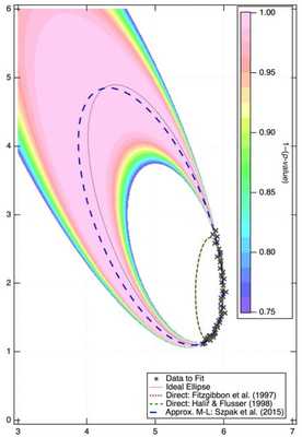 Figure 1: Example ellipse fits to noisy, incomplete data. The data (thick ×) are drawn from the “ideal ellipse” which is an ellipse centered at {5,3} (center of the Figure) with axes {4,1.5} and a major axis tilt 110° counter-clockwise from the x axis. The data are sampled only between 0° and 70°. The “Direct” fits of Fitzgibbon et al. (1997) and Halíř & Flusser (1998) are very poor fits when compared with the true ellipse. For fit parameters {x0, y0, Dmaj, Dmin, θ}, both DIR methods return fits of {5.8, 1.9, 1.5, 0.4, 88°}. My implementation of Szpak et al.’s (2015) AML is significantly better, with fit parameters and uncertainties {4.9±0.3, 3.0±0.5, 4.0±1.2, 1.6±0.2, 112±4°}. Szpak et al. (2015) provide the mathematics to give uncertainties on all ellipse parameters and to display the confidence region (rainbow background) which, in this Figure, demonstrates that the true ellipse lies well within the most likely region (p-value of 0.01).
 I came into this work with a preliminary version of the first algorithm and only a concept for the second. Thus, to demonstrate progress, I began with the second. What should have been simple was posing significant problems and led me down a completely different direction: Fitting ellipses is difficult, and the mathematics literature has progressed in the decade since I originally wrote my ellipse-fitting code.
In the late 2000s, I wrote a non-linear least-squares ellipse fit package (a classic, iterative technique), but that code was unreliable, numerically unstable, and slow. I wrote a new code following the technique outlined in Fitzgibbon et al. (1997). The method used matrix manipulation with no iterations to return an ellipse fit – it was fast and I found it to be reliable.
However, I found that some ellipse fits had both major and minor axes smaller than the best-fit diameter of a circle. That should be impossible, and I found that it was happening for craters with very little of the arc of the ellipse covered (an ellipse is drawn between 0° and 360°, and problems were arising when only partial rims, covering, for example, 30° to 70°, were visible). This is relevant to the second code I wanted to develop because the shadow cast into craters by the rim is only a small part of the ellipse. And, what I was finding as I developed the shadow-fitting code was that the ellipse fits being returned were nonsensical.
This led to significant literature review. First, I found that Halíř & Flusser (1998) had identified an error in Fitzgibbon et al. (1997) based on assumptions the latter made that was not always true. So, I programmed their solution, but the problem still arose. I then discovered that both of those papers fit an ellipse with a “Direct” method (“DIR”). It is apparently now commonly known among the small mathematics community that works in this area that DIR methods are heavily biased, and reading the community’s papers and conference abstracts showed they had demonstrated this bias with the exact phenomenon that I had noted above for some of the lunar crater fits: The ellipse fit was much too small when there was an incomplete arc. (Examples are in Szpak et al. (2012a).) Szpak et al. (2012a) explored multiple different types of algorithms – including DIR, consistent adjusted least-squares, renormalization, and approximate maximum likelihood (AML) – and found that the DIR method I was using was the worst of all types.
That led me to Szpak et al. (2012b) who presented a robust, AML method for fitting ellipses to noisy, incomplete data. Szpak et al. (2015) presented an improvement on their earlier work and provided a method to calculate the uncertainty on each ellipse parameter – something the other methods did not – and display a confidence region based on a p-value interpretation of χ2.
The mathematics behind their AML is much more complicated than DIR, from 50 lines of code for Fitzgibbon et al. (1997) to over 1400 lines of code. It is still fairly fast, and I worked to optimize it. This fast, new code is much more reliable and returns uncertainties on the fit parameters – something that was not available with Fitzgibbon et al. (1997).
I was then able to incorporate the ellipse fit algorithm into preliminary versions of the two computer codes that I had originally set out to create: Rim snapping and crater depths through shadows. Unfortunately, due to the time involved tracking down the original issue with the ellipse fits and then working through the new one, neither of the original two objectives were fully accomplished.