Submitted by Michael Rigney on Tue, 11/08/2022
Many manufacturing processes operate using fixed or hard automation equipment that perform production tasks with limited sensory inputs. For more complex applications, simple cameras or sensors can detect an object’s presence, position, size, or thickness. Machine vision solutions can be applied when objects are more complex, less constrained, or their appearance needs to be evaluated. This blog post will review three applications to provide insights into machine vision’s role in advanced automation.
In many manufacturing processes, counting objects or features is often important to ensure part quality or to manage inventory. While it may sound trivial, this is not a practical task for a human when large quantities are involved. For a task such as this to be automated with machine vision, it is first preceded by object segmentation, and this is facilitated by proper application of lighting and imaging techniques.
The goal of image acquisition is to illuminate and capture an image of the subject in a manner that enhances the contrast between features to be detected and the background. Machine vision software is then used to segment and detect features or objects of interest. Measured attributes of each detected object can then be used to determine its quality or identity.
Characterizing Weld Porosity
Consider the detection and assessment of weld porosity as an example. Part shape, variable profile of the weld bead and reflective metallic surfaces make uniform lighting a challenge. Fortunately, pores do not reflect much light – they have a dark appearance.

Weld beads have variable characteristics, but pores (red dots) have a dark appearance that can be identified and measured using machine vision algorithms.
There are a variety of dark regions in the weld bead image above that can be segmented by machine vision. Pores in welds have a characteristic size range and shape that can be used to disregard dark regions that do not match pore characteristics. Once pores are found, the number of pores in the weld bead and the density (number per inch) can be used to signal whether the weld process is acceptable or requires intervention by an operator or control system.
Counting Tubes
A related example is to count tubes in an image captured from the end of a crate; an accurate count is required for inventory control. Challenges include variable illumination and variable perspective of the tube ends within the image. A tube end can be characterized by its dark interior surrounded by the bright circular face of the tube wall.
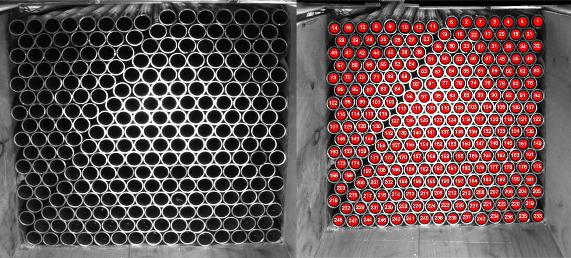
Challenges of counting tubes with machine vision include variable illumination and variable perspective of the tube ends within the image.
Segmenting dark regions with a round shape of an expected diameter will detect most of the tubes. Notice, though, the bright reflections inside some tubes near the bottom of the crate – image processing operations can merge these small features with the tube interior region, enabling robust detection and counting.
The two examples above deal with features having constrained sizes and shapes, making the detection task more amenable to a procedural machine vision solution. The final example, below, is much less constrained.
Detecting Damage on Complex Shapes
Consider detection of surface damage on propeller blades. Damage can vary widely from narrow scratches to large, abraded patches; there are no criteria to describe the expected size or shape of a damaged region. In addition, the complex shape of a propeller blade presents a challenge to optimal illumination for damage contrast enhancement.
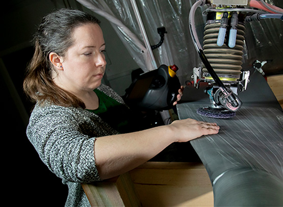
Humans can see damage to a propeller blade under normal light and feel damaged areas with touch. Machine vision requires appropriate imaging and algorithms to detect damage.
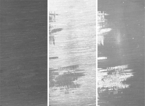
The propeller region was imaged with three lighting orientations. Surface damage may be hidden or visible based on camera, surface and lighting orientations.
The second image above shows the same small blade region illuminated by the same lamp, but from different directions. The damage is practically imperceptible under the lighting configuration used for the left-most (darkest) image. Two alternate lighting directions provide good contrast between the damaged and undamaged blade regions, but the contrast has flipped between the two configurations. Different regions of the propeller blade will exhibit differing responses like those in the figure due to the local surface and damage orientations relative imaging system – meaning there is not a single optimal illumination configuration.
The high variability between damage shape, size and contrast makes automated detection challenging using a procedural programming approach, as was used in the weld porosity and tube counting examples. Southwest Research Institute developed a detection system using machine learning techniques. A convolutional neural network (CNN) identified potential damage regions within an image. A secondary deep neural network classified images as containing damage (or not) based on feature values produced by the CNN. The networks were trained using a large set of images in which damage regions had been manually identified.

A convolutional neural network (CNN) identified potential damage to regions within an image. The CNN algorithm was trained by comparing monochrome images under varying lighting. A secondary deep neural network classified monochrome images as containing damage (or not) based on feature values produced by the CNN.
Beyond Monochrome Vision
The three examples above illustrate a few monochromatic machine vision applications. Things become even more interesting when working with color contrast or using non-visible parts of the spectrum. Monochrome cameras, for example, are sensitive to near-infrared (NIR) wavelengths, allowing for normally invisible or distracting features to be exploited or removed by using or rejecting this band with a spectral filter.
Standard color cameras utilize overlapping broadband red, green, and blue filters; color discrimination can be improved using narrower-band RGB LED illuminators instead of broadband white illumination. Multi-spectral cameras provide highly sensitive color discrimination in comparison to color cameras, and NIR bands can be included. Fluorescent properties of certain inks, dyes and adhesives can be exploited using UV illumination with an appropriate spectral filter. And don’t forget about polarization! Infrared imaging (long-, mid-, short-wave bands) can be used to measure surface temperatures, detect sub-surface features/defects, detect hydrocarbon gas, and more.
It's wonderful to be an engineer in this vast playground of lights, cameras, and actions! To learn more about machine vision technologies, contact Sarah Rogers or visit Machine Learning Technologies and Sensing & Perception.